K3R072 Mimic Display board
87
Siemens Building Technologies 007831_a_en_--.doc
Fire & Security Products 03.2004
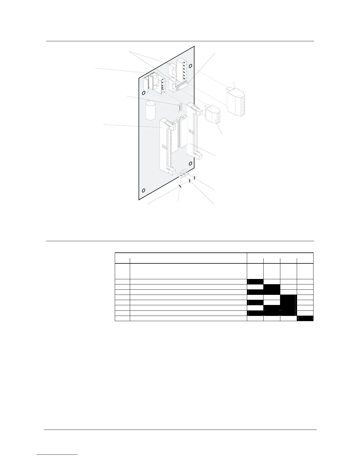
22.6 Important components
Connector "ST1" / "ST2":
Connection of data bus via flat cable
Betriebs LED
NC
49
50
49
Fuse F1 0.4A/T
Supply input 9...45VDC
Plug-in terminals "K1", 4-pin:
Power supply 9...45VDC
Plug-in terminals "K2", 6-pin:
Connection of data bus instead of flat cable
Programming switch "S1":
Equipment address setting
(see chapter Programming switch)
Connector "ST11" 50-pin:
for 50-wire flat cable F50F410
with 24 red LEDs for mimic display
and 2 wires 49/50 for 'LED operation'
for flat cable of relay card K3G060
or
Connector "ST12" 50-pin:
for 50-wire flat cable F50F410
with 24 red LEDs for mimic display
and 2 wires 49/50 unused
for flat cable of relay card K3G060
or
Plug-in connector "X49":
Output for 'Buzzer'
Plug-in connector "X50":
Input for key 'Lamp test'
Plug-in connector "X55":
Input for key 'Switch-off buzzer
Resistor array (assembled ex work /
must be assembled only for device)
one
use Z3I520
1
6
1
4
K2
ST2
F1
ST1
K1
ST12
S1
ST11
X49
X50
X55
K3R072
ON
1
22.7 Programming switch ”S1”
To set equipment address.
Function Programming switch S1
No. S1-1 S1-2 S1-3 S1-4
0 Test procedure
In this setting all outputs are activated
alternating between even and uneven
numbers.
off off off off
1 Equipment address 1 on off off off
2 2 off on off off
3 3 on on off off
4 4 off off on off
5 5 on off on off
6 6 off on on off
7 7 on on on off
8 8 off off off on
”S1-1...4” are set to ”off” at the factory