E3L030 Control module VdS
61
Siemens Building Technologies 007831_a_en_--.doc
Fire & Security Products 03.2004
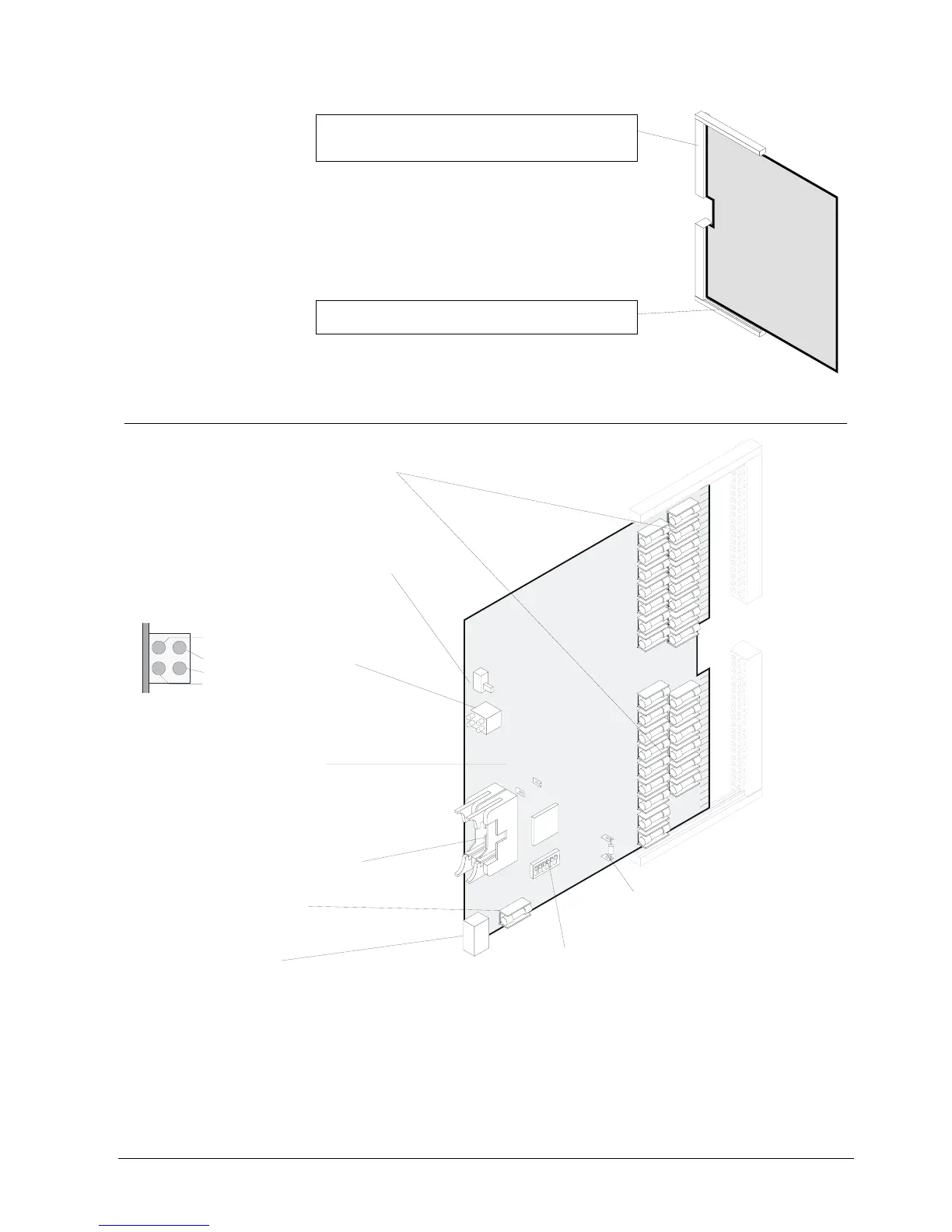
Terminal blocks X1 and X2 (20 terminals each)
- mounted on module chassis
- for direct connection of the periphery
Card chassis
- mounted on module chassis
X2
X1
E3L030
15.4 Important components
Fuses
F1, F3...F23, F25, F27...F30 1A/T
F2, F24, F26 2A/T
F31 2A/T Module supply
Fuses with high breaking capacity (sand-filled)
Flat cable header "ST1" (26-pin): I-Bus
Plug-in terminals "K1":
Supply for "I-Bus" modules
LED indicator block
Programming switch "S3":
Setting "I-Bus address" (see chapter Programming switch)
Fuse
F31 2A/T Module supply
Fuse with high breaking capacity (sand-filled)
0
Ω
-Resistor "X12"
For the allocation of "LED4" active when the
E3L030 is in emergency operation mode (LED4 is
provided as a "spare" in FBF).
0
W
-Resistor "X12" inserted:
LED 4 is active when E3L030 is in emergency operation
mode (fault)
0
W
-Resistor "X12" not inserted
(factory set)
Switch “S1”:
manual unlocking of FSD
(Position "down" = Normal operating mode)
Resistor “R191” (3k32):
for SST fitted at the factory, possibly
remove depending on 3rd party
extinguishing system
yellow "Emergency operation E3L030 or
B3Q700"
green "Activate unlocking"
red "Activate extinguishing"
red "Activate ÜE"
H2
H1