K3R072 Mimic Display board
86
Siemens Building Technologies 007831_a_en_--.doc
Fire & Security Products 03.2004
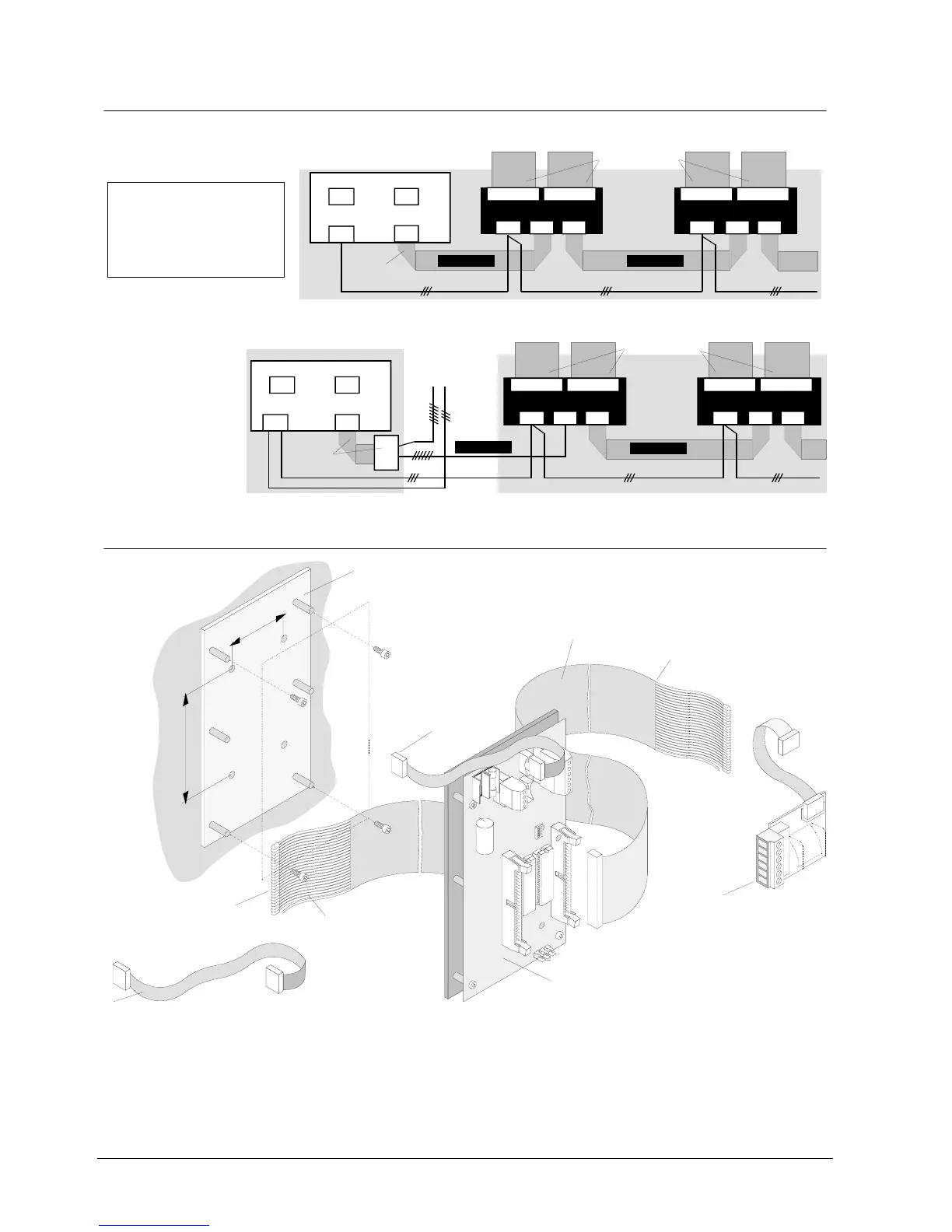
22.4 Wiring principle
LED flat cable
F50F410
F12A100: 0,4m
F12A470: 1,5m
24V
Data bus Data bus
B3Q700
K7 ST4
K3I050
K1 ST2
or
Control console and Mimic Displa
board separate from the control console
Note:
one
-Max. 24 units B3R051 or
K3R072 (also mixed)
possible with max. 8 different
addresses
-remove resistor array except
on unit
Equipm.1
K1 K2
K3R072
ST2
ST11 ST12
K1 ST2ST1
Equipm. 2
K3R072
ST11 ST12
Equipm. 1
K1 ST1
K3R072
ST2
ST11 ST12
K1 ST2ST1
Equipm. 2
K3R072
ST11 ST12
22.5 Mechanical design
24 LEDs
for operation-LED:
wire 49= -
wire 50= +
K3R072 Electronics board
Adapter Z3I530
Flat cable -> terminals:
connection of data bus
housing
outside
Flat cable F12A100 (length 0,4m) / F12A470 (length 1,5m):
connection of data bus housing
inside
F12A100/F12A470
Mounting plate with mounting holes and spacer bolts
Flat cable F50F410: 50-wires
with 24 red LEDs, length 1,0m
the wires can be
separated
60
120
1
6