K3R072 Mimic Display board
88
Siemens Building Technologies 007831_a_en_--.doc
Fire & Security Products 03.2004
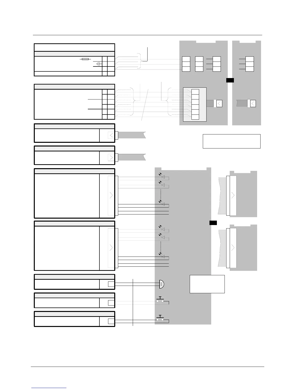
22.8 Connections
K3R072
1
2
3
4
+
Plug-in terminals
K1
24V
Supply 9...45VDC
0V
Flat cable header
ST1
from B3Q700 "ST4"
or
from K3I050 "ST2"
to other K3R072/B3R051
F1
Data bus (via flat cable)
1
2
3
4
5
6
Plug-in terminals
K2
(Clock)
Data bus (via terminals)
(Data)
(Load)
Parallel derivation
permissible
1
2
3
4
5
6
B3Q700
"ST4"
max. 1000m
Flat cable header
ST11
unused
if K3R072
separate
use flat cable
F50F410
Flat cable header
ST2
Connector
X49
Output for buzzer
max. 12mA / 24V
Connector
X50
Input lamp test
Connector
X55
Input switch-off buzzer
Key 'Lamp test'
Key 'Switch-off buzzer'
Buzzer
Mimic Display panel
LED 2
LED 1
Outputs 1-24
max. 12mA / 3,6V
B3Q700
K7-1
K7-2
K7-3
oder
K7-4
K7-5
K7-6
if K3R072
in the vicinity
K1-4
K7-5
K1-1
to other K3R072
Adapter Z3I530
Short-circuit proof
inputs/outputs only
for housing
application
inside
LED 24
LED 'Operation'
(Option, LED not
equipped)
49
50
Flat cable header
ST12
LED 2
LED 1
Outputs 25-48
max. 12mA / 3,6V
LED 24
49
50
1
1
unused
ST1
ST1
K3G060
K3G060
Activation
Relay
1...24
K3I050
K1-3
K1-4
K1-2
K3I050
"ST2"
or
Data bus (via flat cable)
use flat cable
F50F410
Note:
one
Remove eventually resistor array.
Must be assembled for device!
or
-
use Z3I520
12 pin
12 pin
50 pin50 pin2 pin
2 pin 2 pin
Activation
Relay
25...48