E3H020 C-Bus Gateway
53
Siemens Building Technologies 007831_a_en_--.doc
Fire & Security Products 03.2004
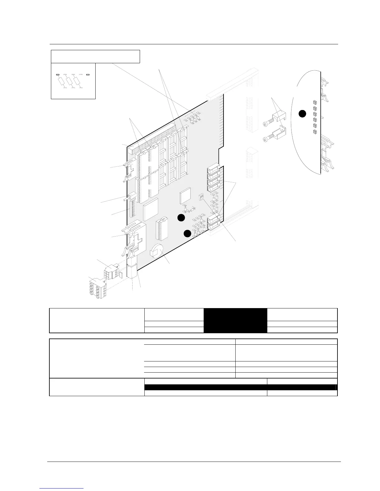
13.6 Important components
Connector "ST2" (14-pin):
unused
Fuses
R
1
1
2
R
1
1
3
R
1
1
1
LP1LP2LP3LP4LP5
LP6LP8
LP7
RAM size 512k
factory set
Positioning of
0-
Ω
-Resistors R111, R112 and R113
Double flat cable header "ST1"
(26-pin): I-Bus
Plug-in terminals "K1":
Supply line from I-Bus
Plug-in terminals "K2"
Programming switch "S3":
"Station address" setting
(see chapter
Programming switches)
Key "S4":
Reset
Connector (96-pin) "ST10":
for interface extension
EPROM plug-in spaces EVEN / ODD:Software
Lithium battery 3V / 70mAh:
RAM buffering and clock supply
- data safeguarded: minimum 2 weeks, typical >100 days
- maintenace free
Programming switch "S5":
RS232 interfaces (see chapter
Programming switches)
3-pin female connector
with 2-pin jumper
4-pin female connector
RAM plug-in spaces (static RAM)
4 pcs 512Kx8Bit / Pos. D11,D12, D15, D16
(ex works)
H1
H6
X2
1
1
3
2
ST10
ST2
LP5
LP1
EVEN
EPROM
RAM
RAM
S4
S3
ST1
X18
X17
X15
X16
R180
R183
S5
F5
F6
F4
F2
F1
F3
ODD
R113
R112
R111
E3H020
Clock
ON
1
1
ON
11
12
15
16
R173
R174
R178
R177
K1
1
4
K2
1
3
µ
P
ASIC
C-Bus
1
1
Mounting bracket for ter
minal blocks "X1" + "X2"
F1...F4 2A/T Emergency operation lines
F5, F6 0,8A/T Supply input
Fuses with high breaking capacity (sand-filled)
Position
Impedance value 110Ω,
e.g. for G51 0.6mm ø
Impedance value 50Ω,
e.g. for MICC
R180 / 183
402Ω 182Ω
➊ Resistors to modify the C-Bus imped-
ance:
R173 / 174 / 177 / 178
110Ω 49.9Ω
Impedance adaptation only required if C-Bus line is > 100m. For other impedance values than 110Ω or 50Ω consult document 007836
H1 yellow gateway ”down” / emergency operation
H2 green normal operation
(fast flashing: no data loaded yet;
slow flashing: data loaded)
H3 yellow network fault
H4 yellow network fatal fault
➋ LEDs H1... H6 at rear side:
H5+6 yellow unused
Use of E3H020 0Ω−Resistors
”FG” + supply from control unit (Input) (X1-17.. 20) X15 + X16 + X17 + X18
➌ Programming of X1:
”FG” + autonomous supply (Output) (X1-17.. 20) Y15 + Y16 + Y17 + Y18