B3R051 Parallel indicator panel
84
Siemens Building Technologies 007831_a_en_--.doc
Fire & Security Products 03.2004
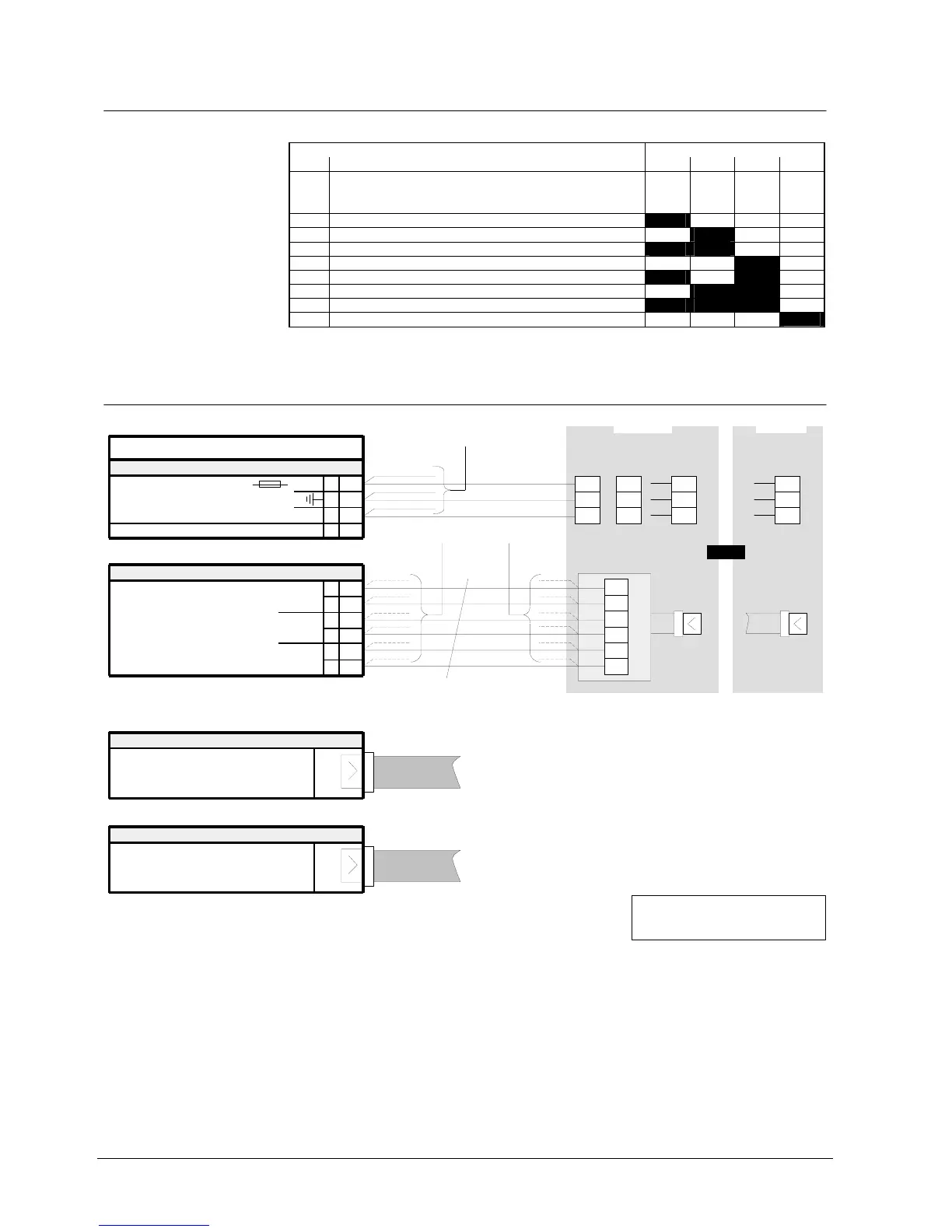
21.7 Programming switch ”S1”
To set equipment address.
Function Programming switch S1
No. S1-1 S1-2 S1-3 S1-4
0 Test procedure
In this setting all LEDs are activated
alternating between even and uneven
numbers.
off off off off
1 Equipment address 1 on off off off
2 2 off on off off
3 3 on on off off
4 4 off off on off
5 5 on off on off
6 6 off on on off
7 7 on on on off
8 8 off off off on
”S1-1...4” are set to ”off” at the factory
21.8 Connections
B3R051
1
2
3
4
+
Plug-in terminals
K1
24V
Supply 9...45VDC
0V
Flat cable header
ST1
from B3Q700, ST4
or
from K3I050, ST2
ST2
to other B3R051/K3R072
F1
Data bus (via flat cable)
1
2
3
4
5
6
K2
(Clock)
Data bus (via terminals)
(Data)
(Load)
unused
Note:
one
Remove eventually resistor array.
Must be assembled for device!
-
parallel derivation
permissible
1
2
3
4
5
6
B3Q700
"ST4"
max. 1000m
if B3R051
separate
B3Q700
K7-1
K7-2
K7-3
or
K7-4
K7-5
K7-6
if B3R051
in the vicinity
K1-4
K7-5
K1-1
to other B3R051