E3G050 Control module ”Contacts”
65
Siemens Building Technologies 007831_a_en_--.doc
Fire & Security Products 03.2004
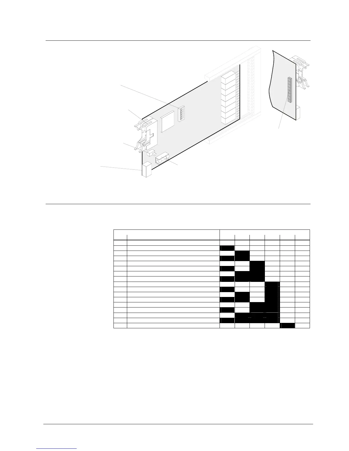
16.3 Important components
Flat cable header "ST1" (26-pin): I-Bus
Plug-in terminals "K1":
Supply for "I-Bus" modules
Maintenance switch "S2":
To switch on maintenance LEDs for test
purposes. In addition to the relay output,
it also enables activation of the
corresponding LED (H1...H8)
= LED (H1..H8) lights if output
is activated.
S2-on
Test LEDs H1...H8 at rear.
Allocation of the individual
LEDs see chapter Connections
Programming switch "S3":
"I-Bus address" setting
(see below)
Fuse
F1 0.5A/T Module supply
H1
H8
F1
S2
K1
1
4
ON
ON
1
S3
E3G050
ST1
ASIC
I-Bus
16.4 Programming switch ”S3”
To set I-Bus address. Each element (module) connected to the I-Bus must have an
individual address (number). This is set on programming switch ”S3”. Maximum 16
I-Bus devices.
Function / I-Bus address Programming switch S3
No. S3-1 S3-2 S3-3 S3-4 S3-5 S3-6
0 Module out of commission (unused) off off off off off off
1 I-Bus user number 1 on off off off off off
2 2 off on off off off off
3 3 on on off off off off
4 4 off off on off off off
5 5 on off on off off off
6 6 off on on off off off
7 7 on on on off off off
8 8 off off off on off off
9 9 on off off on off off
10 10 off on off on off off
11 11 on on off on off off
12 12 off off on on off off
13 13 on off on on off off
14 14 off on on on off off
15 15 on on on on off off
16 16 off off off off on off
”S3-1...6” are set to ”off” at the factory