B3Q700 Control terminal to FC/FT
78
Siemens Building Technologies 007831_a_en_--.doc
Fire & Security Products 03.2004
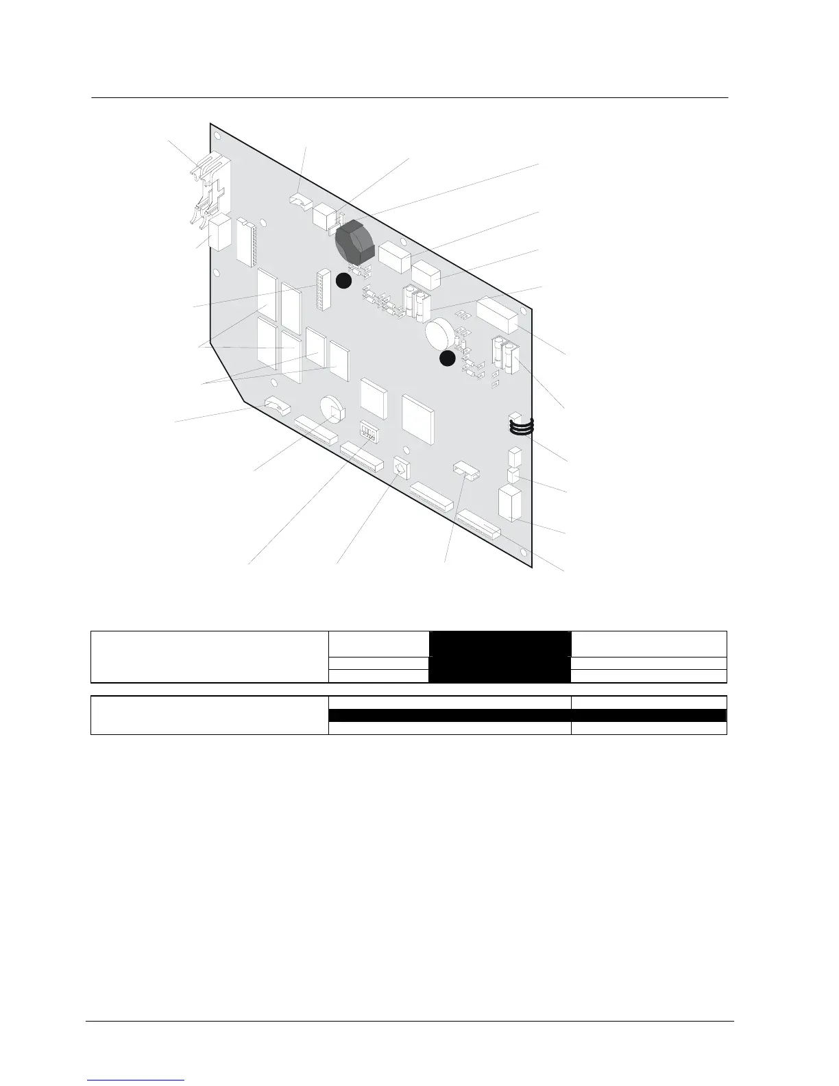
20.6 Important components
1
2
1
3
1
6
1
4
B3Q700
ST1.A
ST1.B
K1
Clock
ST3
K4
K5
K6
K7
F4
F3
ASIC
I-Bus
S1
F1
F2
X34
X33
ON
1
S5
V2
V4
V3
V5
ST2
ST4
ST7
K2
R50
R49
V1
R31
R32
R33
R34
µ
P
Y33
Y34
X31
X32
Y31
Y32
X30
ST8
1
4
1
4
Connector 'V2'.....'V5':
Foil-covered keys (front panel)
Connector 'ST4':
Illumination for LCD
Connector 'ST7':
unused
Plug-in terminals 'K2':
(black 4-pin)
Inputs 'Monitoring
power supply'
:
Jumper 'X30':
Ground fault monitoring 'C-Bus
''J1' = not monitored
'J2' = monitored
'removed' = the other monitored
(ex stock)
(for application details see
chapter ground fault monitoring)
Plug-in terminals 'K5':
(grey 4-pin) "C-Bus"
Plug-in terminals 'K4':
(orange 2-pin):
"External operation enabling"
Connector 'ST3':
Parallel indicator panel B3R051,
Mimic display board K3R072
Plug-in terminals 'K6':
(orange 5-pin):
'Emergency operation circuit'
Fuses 'F1' , ' F2' 0.8A/T:
Supply input / supply output
with high breaking capacity
(sand-filled)
Double flat cable
header 'ST1':
(26-pin): I-Bus
Plug-in terminals 'K1':
(orange 4-pin)
Supply for the
modules 'I-Bus'
Connector 'ST2':
RS232 (2 x HCMOS-Pegel),
connection to E3I020, is also
used as interface to maintenance PC
Switch 'S5': 'Service funktions'
(Details see chapter Programming switches)
Connector 'V1': LCD
Key 'S1': Reset
1
Fuses 'F3', 'F4' 0.5A/T:
Input/output emergency operation
circuit
Fuses with high breaking capacity
(sand-filled)
2
Plug-in terminals 'K7':
(orange 6-pin):
'24V supply voltage'
(18...45VDC)
Connector 'ST8': FBA-CH
unused
SRAM: User data
and Standard text
2MBx8Bit
Flash-ROM 2MBx8Bit:
Software
Rechargeable Lithium battery 3V / 70mAh:
RAM buffering for clock, user data etc.
- data storage time: minimum 2 weeks,
typically >100 days
- maintenance not required
Position Impedance value
110Ω, e.g. for G51 0.6Ø
Impedance value 50Ω,
e.g. for MICC
R49 / 50
402Ω 182Ω
➊ Resistors to modify the C-Bus impedance:
R31 / 32 / 33 / 34
110Ω 49.9Ω
Impedance adaptation only required if C-Bus line is > 100m. For other impedance values than 110Ω or 50Ω consult document 007836
Use of B3Q700
0Ω−Resistors
”FT” + supply from control unit (Input) X31 + X32 + X33 + X34
➋ Programming of terminals ’K7’:
”FC” + autonomous supply (Output) Y31 + Y32 + Y33 + Y34
If the control terminal B3Q700 is used as replacement for FC700A -> change
the 0Ω−Resistors from pos. X31…..X34 to pos. Y31….Y34