B3R051 Parallel indicator panel
83
Siemens Building Technologies 007831_a_en_--.doc
Fire & Security Products 03.2004
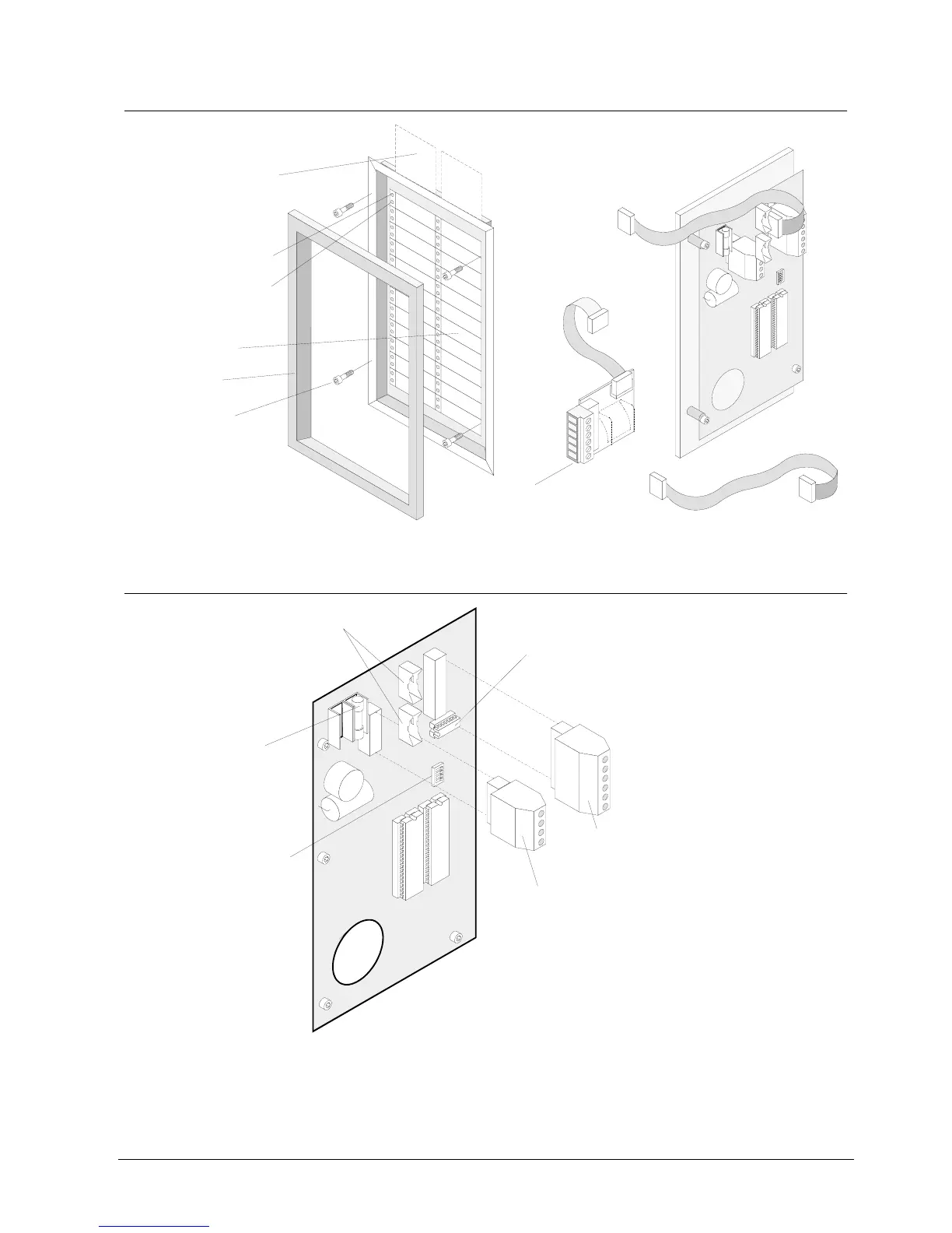
21.5 Mechanical design
Display field 1...24
Blank inscription strips for
insertion can be labelled
Red LED:
Programming depending
on application
Cover frame
4 Mounting screws
View from rear sideView from front side
Flat cable F12A100 / F12A470:
Connection of data bus housing
inside
Adapter Z3I530, flat cable
-> terminals: Connection of
data bus housing
outside
1
2
3
12
13
24
1
6
Yellow LED:
Programming depending
on application
21.6 Important components
1
4
1
6
Fuse F1 0.4A/T:
Supply input 9...45VDC
Connector "ST1" / "ST2":
Connection of data bus via flat cable
Plug-in terminals "K1", 4-pin:
Power supply
Plug-in terminals "K2", 6-pin:
Connection of data bus
instead of flat cable
Programming switch "S1":
Equipment address setting
(see chapter Programming
switch)
Resistor array(assembled ex work /
must be assembled only for device)
one
B3R051
K2
ST2
F1
ST1
K1
S1
ON
1