K3I050 Mimic Display converter
93
Siemens Building Technologies 007831_a_en_--.doc
Fire & Security Products 03.2004
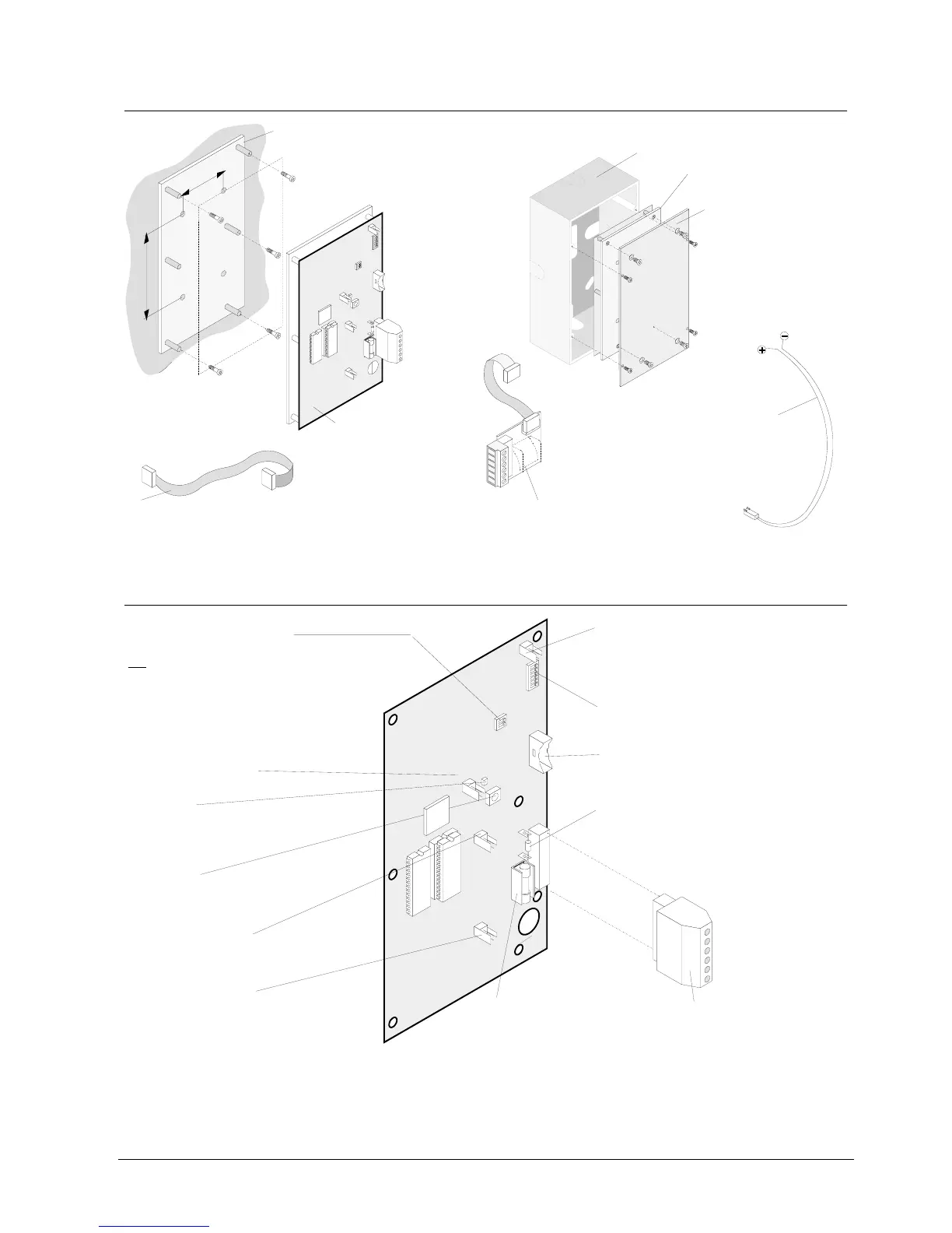
24.5 Mechanical design
60
120
rot
schwarz
Mounting plate with mounting holes and spacer bolts
Adapter Z3I530Flat cable -> terminals:
connection of data bus housing
outside
Cable set Z3I520:
12 pcs. 2-wire cables with
connector, length 0.5m
K3I050 Electronics board
with mounting plate
Flat cable F12A100 (length 0,4m) /F12A470 (length 1,5m):
connection of data bus housing
inside
Plastic housing H23G230
Mounting plate Z3B230:
for the mounting of K3I050
in plastic housing
H23G230
K3I050 Elektronikkarte
1
6
24.6 Important components
Fuse "F1" 1,0A/T:
for supply input 9..45VDC
Plug-in terminals "K1"; 6-pin:
Module supply and LON-Bus
Flat cable header "ST2":
Data bus to modules K3R072 (B3R051)
Plug-in connector "X6":
Buzzer output
Plug-in connector "X7": Operation LED
flashing = parameter download in process
steady = normal operation
(inactive on communication break)
Plug-in connector "X8":
Buzzer off key input
Plug-in connector "X9":
Lamp test key input
Resistor "R1" 100 :
EOL (LON-Bus)
to be removed, if K3I050 is not the
last device on the LON-Bus in stub line
(see E3I040 chapter Principle wiring)
Ω
:
Programming switch "S3":
"LON-Bus address" setting
(see chapter Programming switch)
Programming switch "S4":
S4-1 = off -> device 1...8 addressed flashing mode
supported
S4-1 = on -> only device 5....8 addressed flashing
mode supported (if programmed)
S4-2 = unused
not
Key "S2":
Service key (not used)
LED "H1":
Fault indicator(lights up or flashes
in case of fault 'LON-chip')
K3I050
X7
S3
S4
ST2
S2
H1
X6
K1
X9
X8
F1
R1
ON
1
ON
1
1
6
LON
P
µ
RAM
EPROM