E3M080 Line module ”Collective”
34
Siemens Building Technologies 007831_a_en_--.doc
Fire & Security Products 03.2004
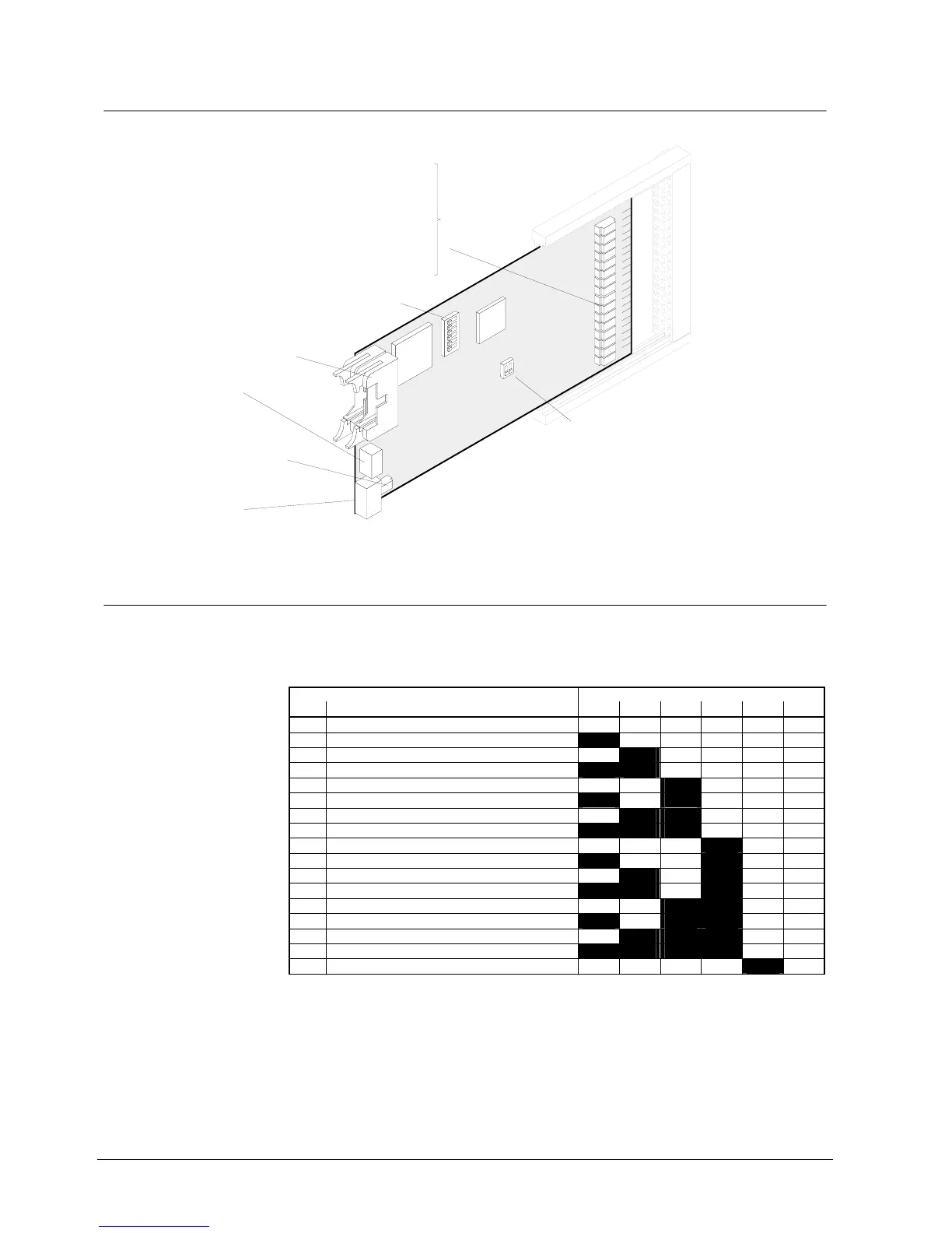
9.6 Important components
Programming switch "S4":
Allows the line short circuit to be evaluated
either as fault or alarm
(common to all 8 lines).
on = Short circuit evaluated as alarm
(AI pulse generator activ)
off = Short circuit evaluated as fault
= no function
set to "off" at the factory
S4-2
S4-1
S4-2
Sicherungen
F1 / F2 1A/F Line 1
F3 / F4 1A/F Line 2
F5 / F6 1A/F Line 3
F7 / F8 1A/F Line 4
F9 / F10 1A/F Line 5
F11 / F12 1A/F Line 6
F13 / F14 1A/F Line 7
F15 / F16 1A/F Line 8
SMD fuses
(can only be
changed at factory)
Fuse
F17 1A/F Module supply
SMD fuse
(can only be changed at factory)
Flat cable header "ST1" (26-pin):
I-Bus
Plug-in terminals "K1":
Supply to "I-Bus" modules
Connector "ST10":
unused
Programming switch "S3": "I-Bus address" setting
(see chapter programming switch)
E3M080
F16
F1
S4
ST10
ST1
S3
K1
1
4
1
1
ON
ON
ASIC
I-Bus
µ
P
9.7 Programming switch ”S3”
To set I-Bus address. Each element (module) connected to the I-Bus must have an
individual address (number). This is set on programming switch ”S3”. Maximum 16
I-Bus devices.
Function / I-Bus address Programming switch S3
Nr. S3-1 S3-2 S3-3 S3-4 S3-5 S3-6
0 Module out of commission (unused) off off off off off off
1 I-Bus user number 1 on off off off off off
2 2 off on off off off off
3 3 on on off off off off
4 4 off off on off off off
5 5 on off on off off off
6 6 off on on off off off
7 7 on on on off off off
8 8 off off off on off off
9 9 on off off on off off
10 10 off on off on off off
11 11 on on off on off off
12 12 off off on on off off
13 13 on off on on off off
14 14 off on on on off off
15 15 on on on on off off
16 16 off off off off on off
”S3-1...6” are set to ”off” at the factory