E3G060 Control module ”Monitored”
68
Siemens Building Technologies 007831_a_en_--.doc
Fire & Security Products 03.2004
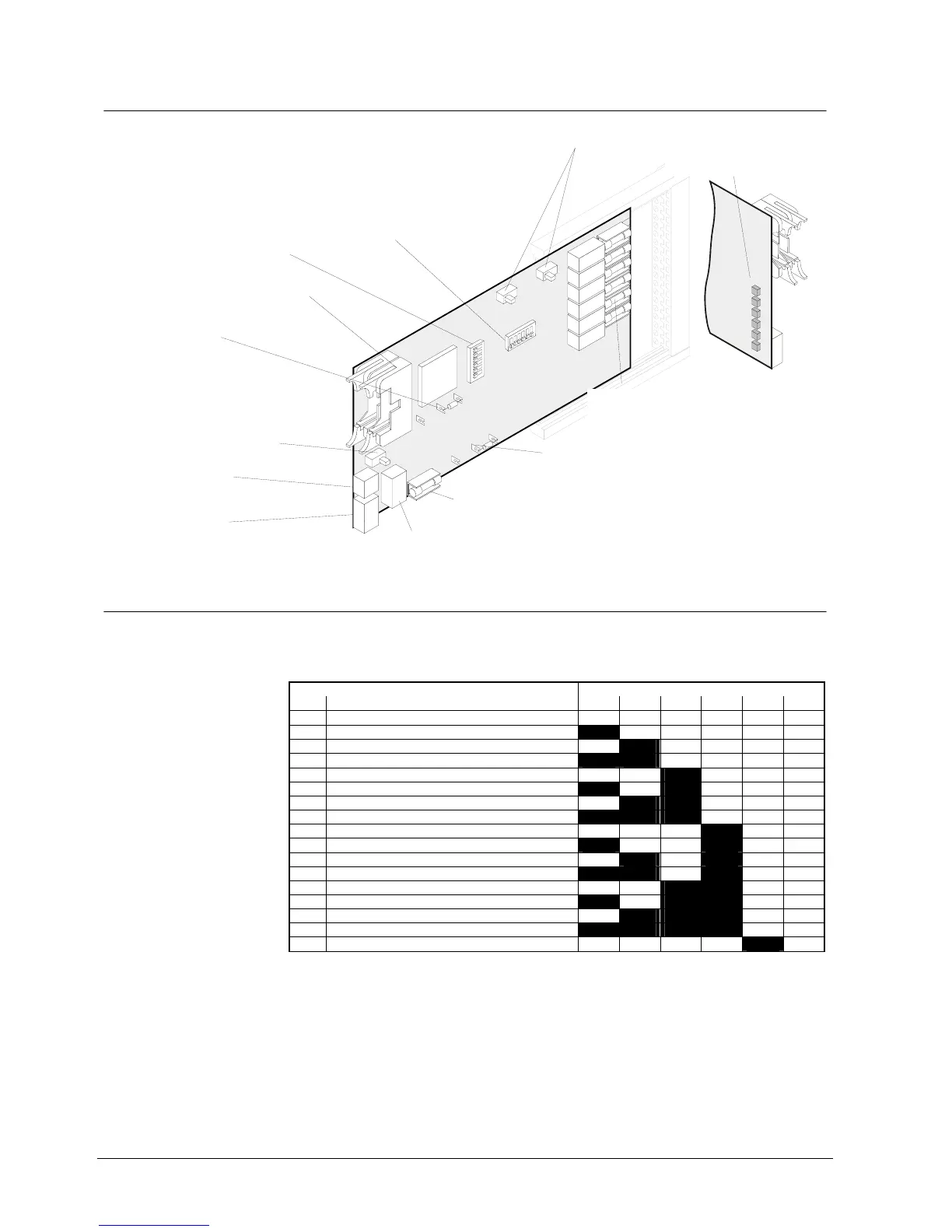
17.4 Important components
i
n
t
e
r
.
H
o
r
n
c
o
n
s
t
.
H
o
r
n
i
n
t
.
O
s
c
i
.
e
x
t
.
O
s
c
i
.
H1
H6
ST1
S8
S6
S7
F1
F3
F5
F7
F9
F11
S3
X12
Y12
X11
Y11
S2
F19
ON
ON
1
1
ON
K1
K2
K3
1
4
1
2
4
1
E3G060
Fuses
F1, F3, F5, F7, F9, F11 2A/T
Control lines monitored
Fuses with high breaking capacity (sand-filled
Fuse
F19 6.3A/T for internal module and horn if internal supply (K1)
Flat cable header "ST1" (26-pin): I-Bus
Plug-in terminals "K1":
Supply for "I-Bus" modules
Maintenance switch "S2":
To switch on maintenance LEDs for test
purposes. In addition to the control line,
it also enables the activation of the
corresponding LED (H1...H6)
= LED (H1..H6) lights if the
control line is activated.
S2-on
Programming switch "S3":
"I-Bus address" setting (see below)
Emergency operation
OFF
Programming switch "S6":
If required, the 6 control lines can also be activated even if an alarm is
given during system malfunction (emergency operation). This function
can be selected for each control line via the "S6" programming switch.
ffiliation: "S6-1" = Control line 1 ...
"S6-6" = Control line 6
" " position = Control line is activated in "Emergency operation mode"
Programming switch "S7" & "S8":
Horn mode setting
(see page
0 -Resistor
Supply for 6 horn outputs (X1-2..14)
X12 = internal supply (factory setting) (K1)
Y12 = external supply (K3)
Ω
Plug-in terminals "K2":
to synchronize Horns or
external oscillator input
Plug-in terminals "K3":
External horn supply
0
Ω
-Resistor
unused
(factory setting X11)
Test LEDs H1...H6 at rear
allocation of the individual
LEDs H1...H6 see chapter
Connections
ASIC
I-Bus
17.5 Programming switch ”S3”
To set I-Bus address. Each element (module) connected to the I-Bus must have an
individual address (number). This is set on programming switch ”S3”. Maximum 16
I-Bus devices.
Function / I-Bus address Programming switch S3
No. S3-1 S3-2 S3-3 S3-4 S3-5 S3-6
0 Module out of commission (unused) off off off off off off
1 I-Bus user number 1 on off off off off off
2 2 off on off off off off
3 3 on on off off off off
4 4 off off on off off off
5 5 on off on off off off
6 6 off on on off off off
7 7 on on on off off off
8 8 off off off on off off
9 9 on off off on off off
10 10 off on off on off off
11 11 on on off on off off
12 12 off off on on off off
13 13 on off on on off off
14 14 off on on on off off
15 15 on on on on off off
16 16 off off off off on off
”S3-1...6” are set to ”off” at the factory