Operation
8.2 Designation and description of the inputs
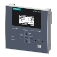
3KC ATC6300 transfer control device
Manual, 03/2018, L1V30535632002A-01
107
The ATC6300 has 6 permanently integrated digital inputs which are designated as INPx. The
number of digital inputs can be increased by using expansion modules. For further
information on the expansion modules, please refer to chapter Expandability by modules
(Page 41) and chapter Expansion modules (Page 175).
Maximum number with
expansion modules
The function of the integrated digital inputs can be freely parameterized by the user:
● Maximum input current: 8 mA
● Maximum signal voltage for <0>: 2.2 V
● Minimum signal voltage for <1>: 3.4 V
● Minimum input signal delay: 50 ms
The following inputs are installed on the ATC6300:
Recommended cable
cross-section
Digital inputs INPx
0.2 - 2.5 mm
2
(24 -
12 AWG)
acc. to UL 508 0.75 -
2.5 mm
2
(18 -
12 AWG)
17 INP3 Digital input 3
19 INP5 Digital input 5
Common control terminal for inputs 1 - 6
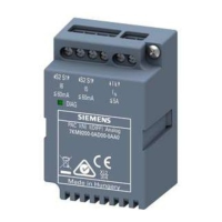
Addressing the expansion modules with digital inputs
If only one expansion module with digital inputs is installed in the ATC6300 it is designated
INP7, 8 ... regardless of whether it is inserted in slot 1 or 2.
If there are 2 modules with inputs in the ATC6300, the module in slot 1 is addressed as
INP7, 8 ... and the module in slot 2 as INP9, 10 ....
Note
Expansion module removed
If there are 2 modules in t
he device and the module in slot 1 is subsequently removed, then
the addressing of the remaining module in slot 2 changes from INP9,10 to INP7, 8. The unit
will point out this change at the necessary restart (see chapter
Behavior of the ATC6300
(Page 44)).
 Loading...
