Functions
5.1 Basic functions
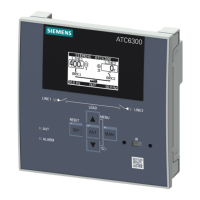
3KC ATC6300 transfer control device
48 Manual, 03/2018, L1V30535632002A-01
The predefined alarms have the following properties:
A01 Battery voltage too low The voltage of the DC supply is below the lower threshold limit for longer than the set
A02 Battery voltage too high The voltage of the DC supply is above the upper threshold limit for longer than the set
time.
A03 Line 1 circuit breaker
timeout
The Line 1 switching device has not performed any opening or closing operation within
the set maximum period. Once the alarm has been triggered, the ON or OFF command
is inhibited. The alarms are only triggered if at least one of the two energy sources is
available, that is to say it is within the limits.
A04 Line 2 circuit breaker
timeout
The Line 2 switching device has not performed any opening or closing operation within
the set maximum period. Once the alarm has been triggered, the ON or OFF command
is inhibited. The alarms are only triggered if at least one of the two energy sources is
available, that is to say it is within the limits.
A05 Line 1 wrong phase
The phase sequence measured on Line 1 does not match the programmed phase
A06 Line 2 wrong phase
The phase sequence measured on Line 2 does not match the programmed phase
A07 Load not powered
timeout
Either because the power supplies were not available, or because both switching de-
vices have remained open, the load has been de-energized for longer than the time
A08 External battery charger
This alarm is triggered by the input programmed for the charger alarm function if at
least one energy source is within the limits.
A09 Emergency Alarm triggered by opening the external emergency input. Both switching devices are
opened (see Table of functions of the digital inputs (Page 108)).
A10 Line 1 breaker protec-
tion trip
The Line 1 breaker has opened because an overcurrent protection device has tripped.
This is signaled by activation of the input with function Line 1 breaker protection trip
(see Table of functions of the digital inputs (Page 108)).
A11 Line 2 breaker protec-
The Line 2 breaker has opened because an overcurrent protection device has tripped.
This is signaled by activation of the input with function Line 2 breaker protection trip.
A12 Line 1 generator not
If the input with the function "Generator ready 1" is opened, this alarm is triggered (see
Table of functions of the digital inputs (Page 108)).
A13 Line 2 generator not
If the input with the function "Generator ready 2" is opened, this alarm is triggered (see
Table of functions of the digital inputs (Page 108)).
A14 Maintenance Hours 1 This alarm is triggered if the maintenance hours for Line 1 reach the value zero. See
Menu P12 - Miscellaneous (Page 139
) Use this in order to reset operating hours and
A15 Maintenance Hours 2 This alarm is triggered if the maintenance hours for Line 2 reach the value zero. See
Menu P12 - Miscellaneous (Page 139
) Use this in order to reset operating hours and
A16 Maintenance operations
This alarm is triggered if the number of operating cycles for Line 1 reaches the value
set in Menu P12. Use command menu to restore operation and reset the alarm.
A17 Maintenance operations
This alarm is triggered if the number of operating cycles for Line 2 reaches the value
set in Menu P12. Use command menu to restore operation and reset the alarm.
A18 Auxiliary voltage failure The device that manages the draw of auxiliary voltage supply from one of the available
lines signals a failure or improper operation.
UA1.
User alarm The user alarm is generated by enabling the variable or associated input in Menu P15.
 Loading...
