Operation
8.3 Designation and description of the outputs
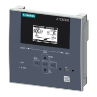
3KC ATC6300 transfer control device
Manual, 03/2018, L1V30535632002A-01
111
The following outputs are installed on the ATC6300:
Recommended
cable cross-
section
Digital outputs
OUTx
OUT 1 Digital output 1 1 NO contact
8 A AC1 250 V AC
8 A DC1 30 V DC
0.2 - 2.5 mm
2
(24 - 12 AWG)
acc. to UL 508:
0.75 - 2.5 mm
2
(18 - 12 AWG)
10
OUT 2 Digital output 2 1 NO contact
8 A AC1 250 V AC
8 A DC1 30 V DC
12
OUT 3 Digital output 3 1 CO contact
8 A AC1 250 V AC
1.5 A AC15 250 V DC
2x 1 NO contacts
8 A AC1 250 V AC
8 A DC1 30 V DC
1.5 A AC15 250 V DC
26 Common control ter-
minal for pins 25 and
2x 1 NO contacts
8 A AC1 250 V AC
8 A DC1 30 V DC
1.5 A AC15 250 V DC
29 Common control ter-
minal for pins 28 and
The function of the outputs can be selected from preprogrammed functions.
The setting is made via the Menu P11 (see chapter P11 - Digital outputs (Page 138)). Every
output can be configured for normal or reverse function (NOR or REV).
Some functions require another numeric parameter. This is specified by parameters by
means of an index.
Note
Use of an index
An index is used if additional functions are to be used as a source for the output.
For example, an output can function as a source for a
counter or for a user alarm.
On replacement or subsequent modification of the modules, attention must be paid to the
addressing. This behaves like the addressing of the digital inputs (see chapter Addressing
the expansion modules with digital inputs (Page 107)).
 Loading...
