Table of contents
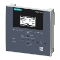
3KC ATC6300 transfer control device
4 Manual, 03/2018, L1V30535632002A-01
5.1.4.1 Enabling additional resources ................................................................................................ 42
5.1.4.2 Inserting an expansion module .............................................................................................. 43
5.1.4.3 Behavior of the ATC6300 after inserting a module ................................................................ 44
5.1.5 Communication COMx ........................................................................................................... 45
5.1.6 Alarms .................................................................................................................................... 46
5.1.6.1 Properties of the alarms ......................................................................................................... 47
5.1.6.2 Alarm description ................................................................................................................... 48
5.1.6.3 Alarm table ............................................................................................................................. 49
5.1.6.4 User alarms ............................................................................................................................ 50
5.1.7 Automatic test ........................................................................................................................ 51
5.1.7.1 Enabling the automatic test .................................................................................................... 51
5.1.7.2 Stopping the automatic test ................................................................................................... 51
5.1.8 Simulation of priority line failure ............................................................................................. 52
5.1.9 Command menu..................................................................................................................... 53
5.1.9.1 Executing a command ........................................................................................................... 53
5.1.9.2 Table of commands ............................................................................................................... 55
5.1.10 Event log ................................................................................................................................ 56
5.2 Extended functions ................................................................................................................ 57
5.2.1 Remote variables REMx ........................................................................................................ 57
5.2.2 User limit LIMx ....................................................................................................................... 57
5.2.3 Counter CNTx ........................................................................................................................ 61
6 Installation ............................................................................................................................................ 63
6.1 Dimensions for the door cutout .............................................................................................. 63
6.2 Installation of the ATC6300 .................................................................................................... 63
7 Connection ........................................................................................................................................... 65
7.1 General connection drawings ................................................................................................ 66
7.1.1 Connection of circuit breakers with motor operator ............................................................... 66
7.1.2 Connection of remotely operated transfer control devices .................................................... 68
7.1.3 Connection of contactors ....................................................................................................... 69
7.2 Connection of the power supply............................................................................................. 70
7.2.1 Implementation of the dual power supply by means of dual network connection
3KC9625-1 (for IEC applications only) .................................................................................. 71
7.2.2 Implementation of the dual power supply by means of a voltage monitoring relay ............... 73
7.2.3 Implementation of the dual power supply by means of an electromechanical relay ............. 73
7.2.4 Implementation of the dual power supply by means of a UPS .............................................. 74
7.2.5 Recommended implementation for gen-set application (with power supply by means of
a DC source) .......................................................................................................................... 74
7.2.6 Recommended implementation for gen-set application (without power supply by
means of a DC source) .......................................................................................................... 75
7.3 Connection of Siemens SENTRON switching devices .......................................................... 76
7.3.1 Accessories for switching devices ......................................................................................... 76
7.3.2 Accessories for mechanical interlocking ................................................................................ 77
7.3.3 Technical specifications of the Siemens SENTRON switching devices in accordance
with IEC 60947-6-1 (IEC only) ............................................................................................... 82
7.3.3.1 Typical operating times of the Siemens SENTRON switching devices in accordance
with IEC 60947-6-1 (IEC only) ............................................................................................... 86
7.3.4 Connection of 3VA molded case circuit breakers .................................................................. 89
7.3.4.1 Connection of 3VA molded case circuit breakers - MO320 (IEC, UL) ................................... 89
 Loading...
