1PXFSTVQQMZ
-PXWPMUBHFEJTUSJCVUJPO
FH5/44ZTUFNା7
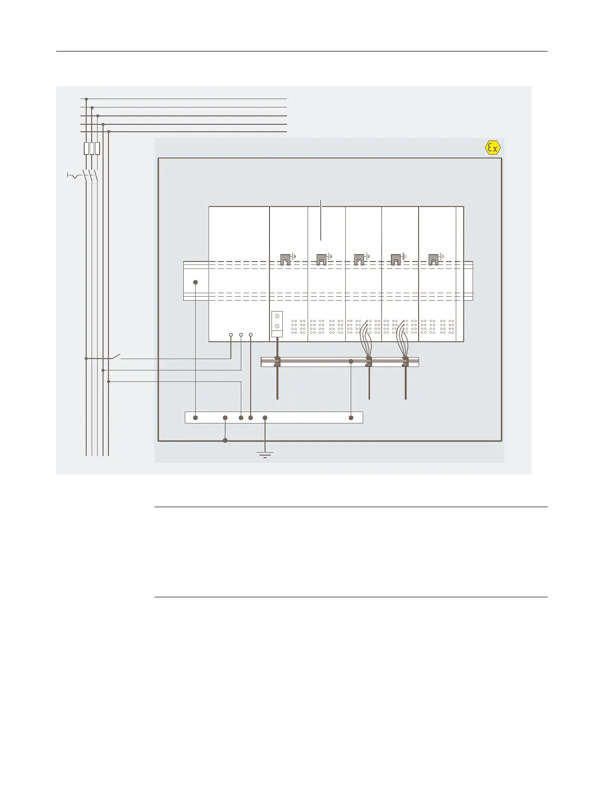
'&'VODUJPOBMHSPVOEGPSEJSFDUEJTDIBSHFPG
JOUFSGFSFODFMFWFMTUPUIFNPVOUJOHSBJMWJB
TQSJOHDPOUBDU
4BGFBSFB
.PVOUJOHSBJMGPS
TVQQPSUJOHDBCMF
TIJFMET
(SPVOECVT1"
#VTDBCMF
)B[BSEPVTBSFB;POF
.PVO
UJOHSBJM
&ODMPTVSF&YF
-
-
-
/
1&
'&'&'&'&'&
-
/
1"
&5J41
14"$7
Figure 6-2 Operating ET 200iSP and PS AC120/230V with equipotential bonding
Note
Requirement for connecting the protective conductor
The connection of the protective conductor to the equipotential bonding rail, EB, is optionally
possible.
A requirement for connecting the PE conductor to the equipotential bonding rail EB is
standard-compliant equipotential bonding of the EB and PE potentials on the line-side.
Equipotential bonding EB
Connect the following to the equipotential bonding EB
• The mounting rail of the ET 200iSP system (with the grounding bolts Ex e)
• The terminal module TM-PS-A via the equipotential bonding connection terminal
Wiring
6.2 Operating the ET 200iSP with equipotential bonding
ET 200iSP
Operating Instructions, 11/2022, A5E00247483-AK 123