Note
Pulling and plugging the ber-optic cable and transceiver during operation (hot-swapping) in
Zone 1 and Zone 2. In Zone 21 and Zone 22, you may only open the enclosure of the ET 200iSP
if no combustible dust is present.
Connecting sensors and actuators (right-hand module)
Refer to the Chapter "Wiring terminal module TM-EM/EM (Page 135)".
Wiring terminal module TM-IM/IM
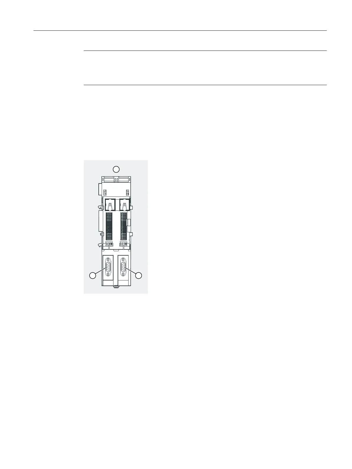
Connect the two bus connectors for the redundant IMs. The procedure is described for the TM-
IM/EM. Repeat the same steps for the right-hand module.
① Terminal module TM-IM/IM
② Connection for IM 152-1DP (b):
PROFIBUS RS 485-IS
③ Connection for IM 152-1DP (a):
PROFIBUS RS 485-IS
Figure 6-7 Wiring terminal module TM-IM/IM (PROFIBUS RS 485-IS)
For pin conguration, refer to the Chapter "Terminal module TM-IM/IM (Page 258)".
6.4.7 Wiring Terminal Modules TM-EM/EM
Properties
The terminal module TM-EM/EM is the interface to the sensors and actuators.
Wiring
6.4 Wiring the ET 200iSP
ET 200iSP
Operating Instructions, 11/2022, A5E00247483-AK 135