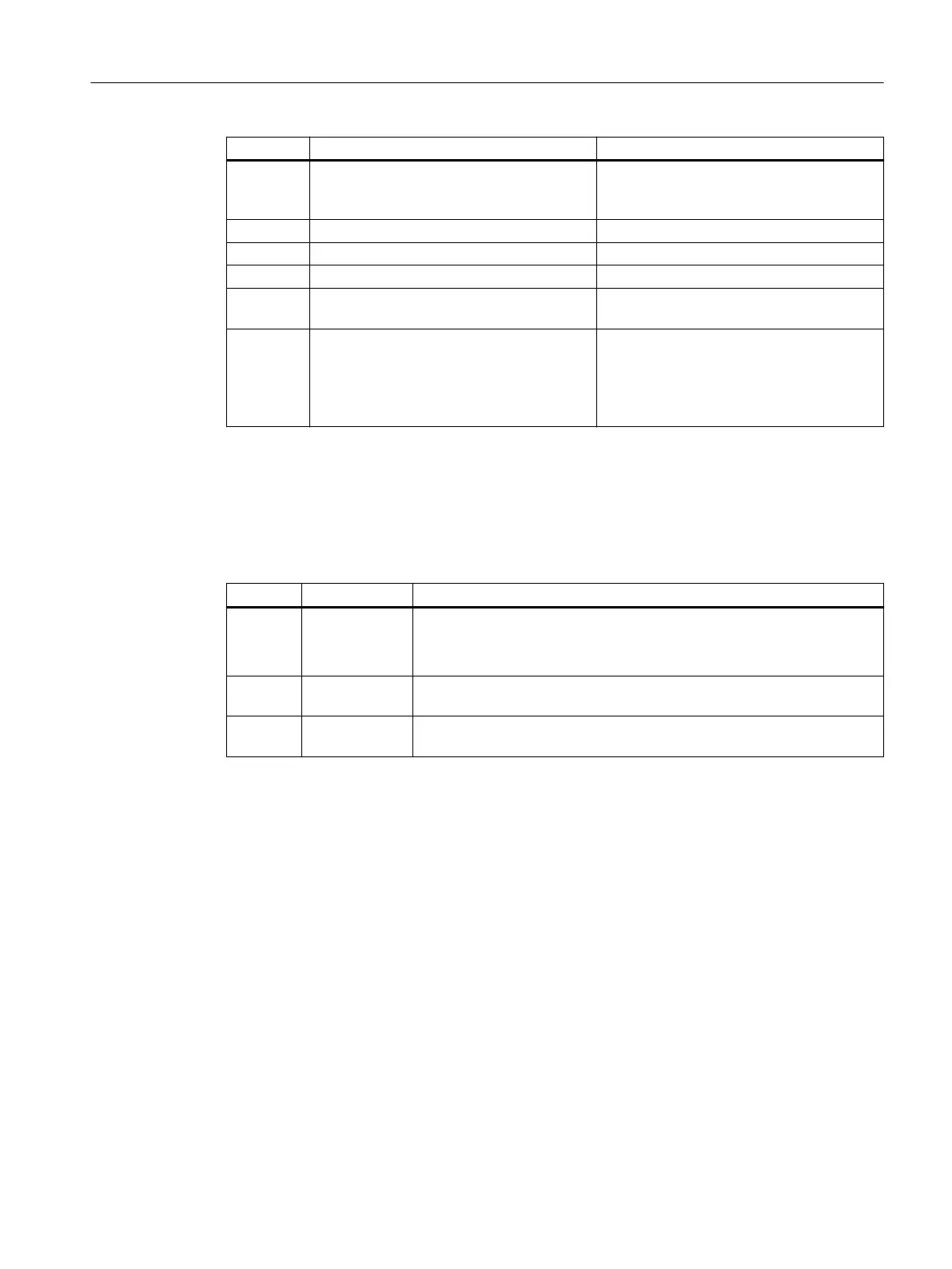
Byte Meaning Comment
5 Write Read Index Oset = 1 (The response to a request data record is
made with the data record number of the
request data record + 1)
6 Index of HMD Feature Parameter = 149
7 Index of HMD Module Parameter = 255 (not relevant)
8 Start Index of Burst Buer Area = 255 (not relevant)
9+n Index of HMD Channel Parameter (Channel
n)
= 131+n
9+n+4 Index of HART Client Channel Message Data = 80+(2*n)
The HART request data sets are not congu‐
rable. The data records from data record
number 80 (80, 82, 84, 86) are permanently
used.
A.6.5 HART feature data
Structure of the HART feature data
Byte Meaning Comment
0 Feature data pa‐
rameter 1
Bit 1 = 1: "Parameter check result is given with a read response"
Bit 5 = 1: "Compact format is supported"
Bit 6 = 1: "SHC mode is supported"
1 Feature data pa‐
rameter 2
0
2 Max Length Da‐
ta Unit
maximum data length of request/response
A.6.6 HART variable data record
The I/O module supports a maximum of 4 HART variables per channel in enabled HART
operation. These variables are read cyclically, provided they are supported by the connected
eld device. These 64 HART variables are made available readable in HART variable data record
121.
Each HART variable consists of a 4-byte real value and one byte of quality code.
In IO redundancy mode, the HART variables are only updated if the HART interface is on the
corresponding module/channel. The channel may not be in standby mode. If the HART interface
is on the partner module/partner channel, the corresponding HART variable is initialized (quality
code = 0x37).
Appendix
A.6 HART operating data records
ET 200iSP
Operating Instructions, 11/2022, A5E00247483-AK 459