7.11.8 Startup of the ET 200iSP with redundancy of the IM 152-1PN
Operating principle
In the case of redundancy, the two plugged IM 152-1PN start up independently of each other.
The following ow diagram shows the startup of the IM 152-1PN (a, left interface module). If we
consider the IM 152-1PN (b, right interface module), the following ow diagram applies
accordingly with reversed designations.
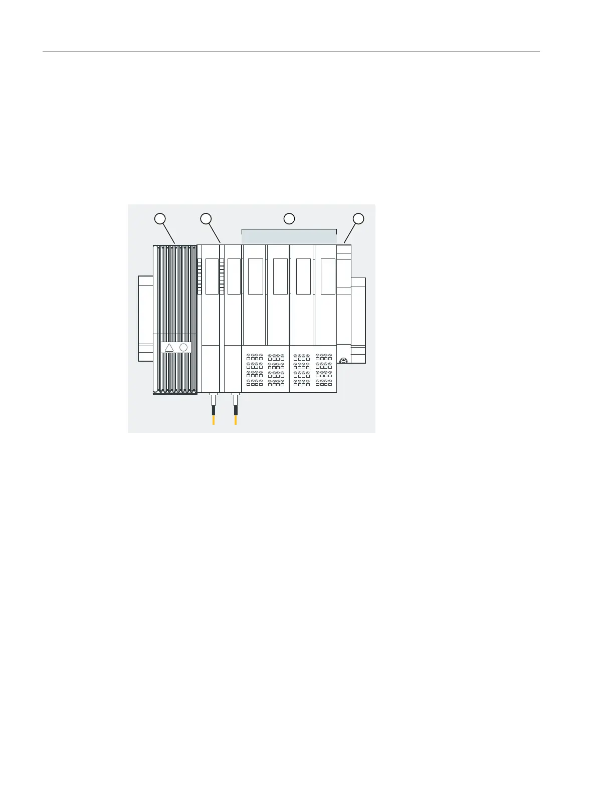
① Terminal module TM-PS-A with PS
② Terminal module TM-IM/IM with interface modules IM 152-1PN (a) and IM 152-1PN (b)
③ Terminal modules TM-EM/EM with electronic modules
④ Terminating module
Figure 7-6 ET 200iSP with PROFINET interface modules
Commissioning and Diagnostics
7.11 Commissioning and starting up the ET 200iSP
ET 200iSP
184 Operating Instructions, 11/2022, A5E00247483-AK