3. Fasten the individual lines in the screw terminal Ex e.
4. Close the terminal cover.
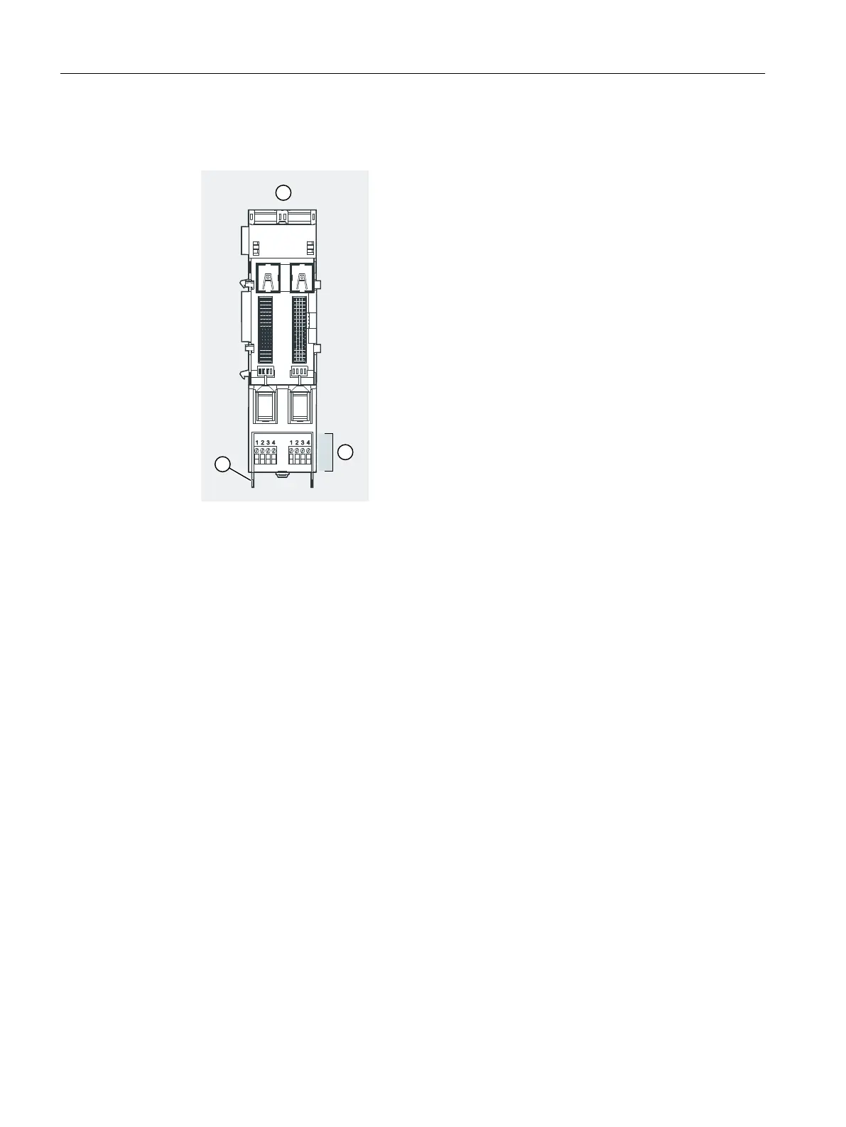
① Terminal module TM-RM/RM
② Connection for electronic module 2 DO Relay UC60V/2A
channels 0 and 1
③ Terminal cover
Figure 6-9 Wiring terminal module TM-RM/RM
Pin assignment, see section Terminal module TM-RM/RM (Page 264).
6.4.9 Connecting cable shields
Properties
The cable shields of the analog electronic modules must be connected to the ground bus
(equipotential bonding) of the enclosure.
Requirements
• Tin-coated or zinc-coated standard mounting rail according to EN 50022 (35 x 15/35 x 7.5)
and xing accessories
• Shield terminals (6ES5728-8MA11)
• Securing the ground cable to the standard mounting rail:
– Zone 1 or Zone 21: Ex e terminal. Use the WP 16/E terminal from Weidmüller (see
Appendix "Article numbers (Page 419)").
– Zone 2, zone 22 or safe area: Normal terminal
Wiring
6.4 Wiring the ET 200iSP
ET 200iSP
138 Operating Instructions, 11/2022, A5E00247483-AK