For conguration with PROFIBUS connection: Connect PROFIBUS RS 485‑IS (left module)
1. Insert the bus connector into the PROFIBUS RS 485‑IS connection.
Note
The cable shield of the bus cable is connected in service to the terminal module TM-IM/EM
by means of a spring contact with the mounting rail and consequently with the equipotential
bonding PA.
2. Use the 3.5 mm screwdriver to tighten the lockscrews of the bus connection (torque: 0.5 to
0.7 Nm).
3. Mark the bus cable as "Ex i bus cable".
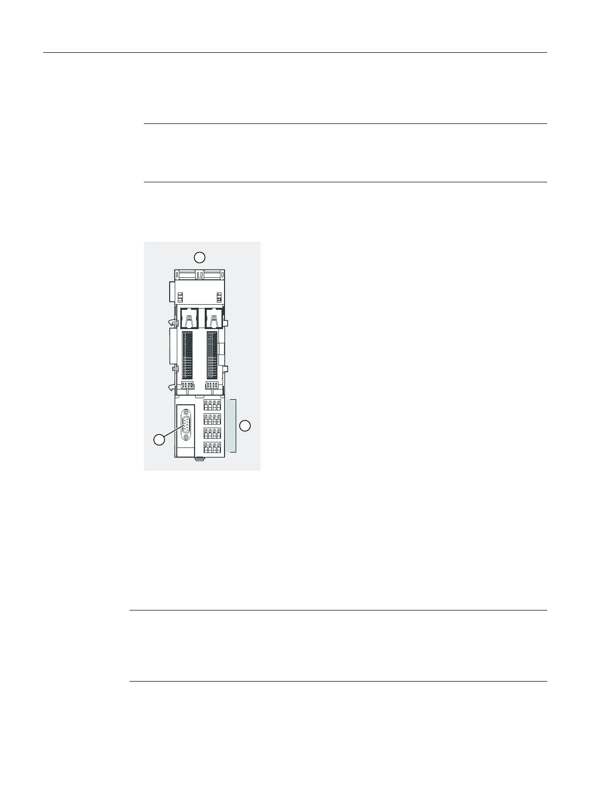
① Terminal module TM-IM/EM
② Connector for the electronic module:
channel 0 to 3, or
channel 0 to 7
③ Connection for IM 152-1DP:
PROFIBUS RS 485-IS
Figure 6-6 Wiring terminal module TM-IM/EM (PROFIBUS RS 485-IS)
For pin conguration, refer to the Chapter "Terminal module TM-IM/EM 60S and TM-IM/EM 60C
(Page 254)".
Note
The PROFIBUS RS 485-IS of the ET 200iSP is intrinsically safe due to the RS 485-IS coupler. It is
therefore permitted to remove and insert the bus connector during running operation in Zone
1 and Zone 2. In Zone 21 and Zone 22, you may only open the enclosure of the ET 200iSP if no
combustible dust is present.
Wiring
6.4 Wiring the ET 200iSP
ET 200iSP
134 Operating Instructions, 11/2022, A5E00247483-AK