Mechanical design
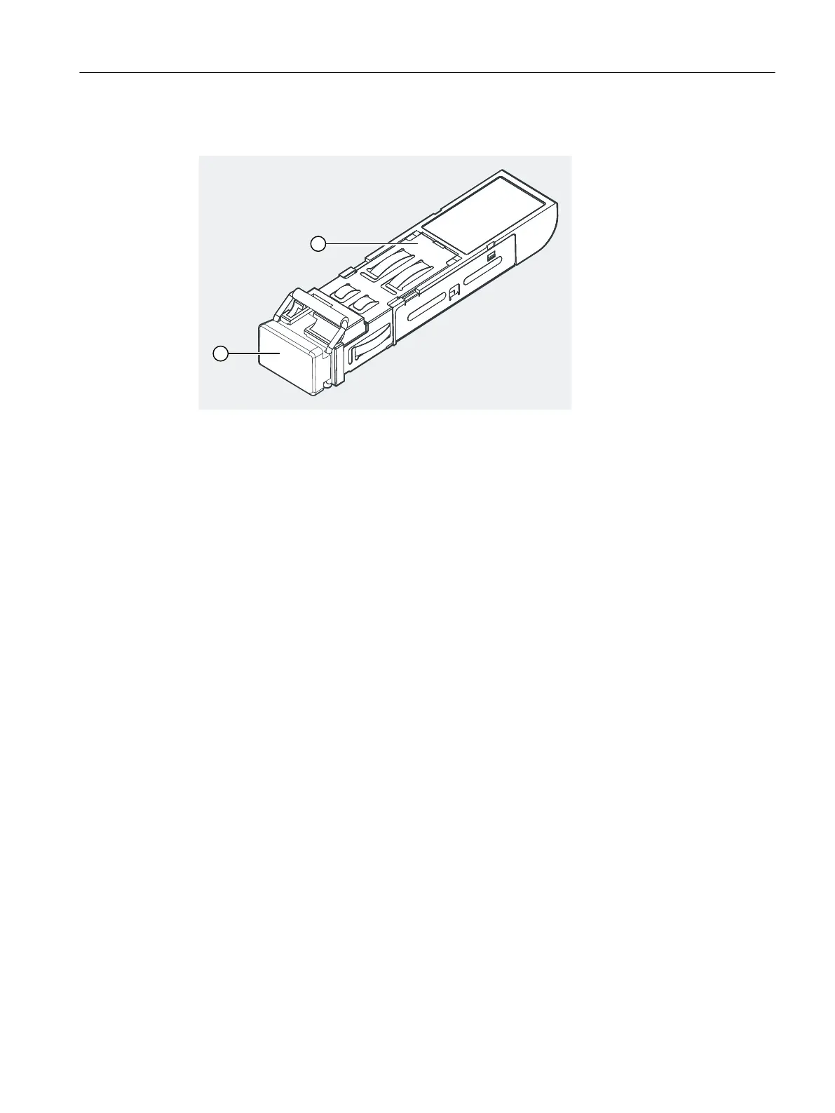
① Blanking plugs
② SFP transceiver
Figure 6-17 SFP transceiver
Unused transceivers must be sealed with blanking plugs to protect the optical interface. The
blanking plugs are located in the optical transceiver when it is delivered.
Inserting and wiring the optical transceiver
1. Remove the blanking plug of the SFP socket of the IM 152-1PN interface module.
2. Insert the optical transceiver into the IM 152-1PN until the transceiver snaps into place.
3. Remove the blanking plug of the optical transceiver.
4. Insert the end of the ber-optic cable into the optical transceiver until the cable snaps into
place.
Replacing optical transceivers
While one transceiver is being replaced during operation, the other transceiver remains plugged
in to maintain device communication.
1. During operation of the IM 152-1PN, check the LED of the other SFP connection to prevent
device communication from being interrupted.
Before replacing transceiver 1, check that the "LK 2" LED is green.
Before replacing transceiver 2, check that the "LK 1" LED is green.
2. Pull the ber-optic cable out of the optical transceiver.
3. Flip the clip of the optical transceiver forward (away from the IM 152-1PN) to unlatch the
transceiver.
If you cannot open the clip with your ngers, use a screwdriver to open the clip.
Wiring
6.5 Inserting and labeling the power supply, interface module, and electronic modules
ET 200iSP
Operating Instructions, 11/2022, A5E00247483-AK 151