Requirements
• The PROFIBUS DP address for the ET 200iSP is set on the interface module via DIP switch. The
DIP switch is located on the front of the interface module, protected by a swivel cover.
• Permitted PROFIBUS DP addresses are 1 to 125
• Each address can be assigned only once on the PROFIBUS.
Required tools
3.5 mm screwdriver
Setting the PROFIBUS DP address
1. To open, swivel the cover to the right.
2. Use the screwdriver to set the desired PROFIBUS DP address using the DIP switches.
3. Close the cover.
Changing the PROFIBUS DP address
1. Use the screwdriver to set the PROFIBUS DP address "0" via the DIP switches.
2. Switch the supply voltage of the ET 200iSP o and on at the power supply PS. The deletion
process is completed when the BF LED ashes (0.5 Hz, duration approx. 10 s).
The ET 200iSP stores the parameters retentively in the ash memory of the IM 152-1DP.
Therefore, you should delete the retentitively stored parameters during the rst
commissioning or after the modication of the plant.
3. Now set the new PROFIBUS DP address via the DIP switches and switch the supply voltage at
the power supply PS o and on again.
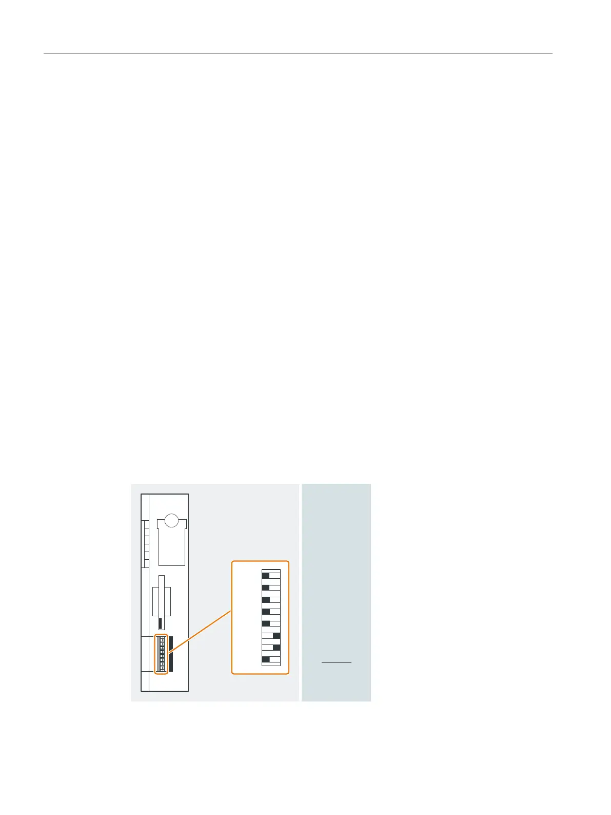
*OUFSGBDFNPEVMF
&YBNQMF
%1BEESFTT
3FTFSWFE
0/0''
Figure 7-3 Setting the PROFIBUS DP address
Commissioning and Diagnostics
7.11 Commissioning and starting up the ET 200iSP
ET 200iSP
180 Operating Instructions, 11/2022, A5E00247483-AK