Digital output module 2 DO Relay UC60V/2A
Table 7-22 Digital output module 2 DO Relay UC60V/2A
Diagnostic message Applicability Can be set
Error Module No
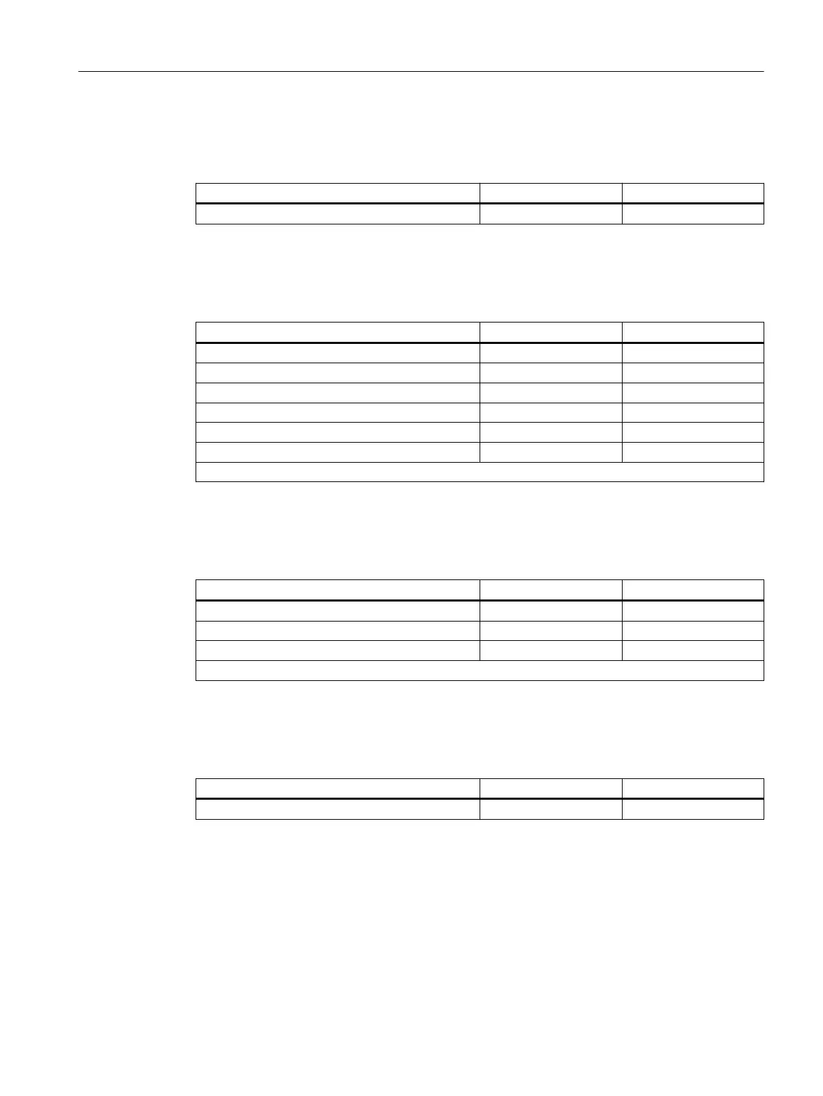
Analog input modules
Table 7-23 Analog input modules
Diagnostic message Applicability Can be set
Short circuit
1
Channel Yes
Wire break Channel Yes
Upper measuring range exceeded Channel Yes
Lower measuring range exceeded Channel Yes
Error Module No
Reference channel error Module No
1
Not possible with 4 AI TC and with 4 AI I 4WIRE HART
Analog output modules
Table 7-24 Analog output modules
diagnostic message
1
Applicability Can be set
Short-circuit Channel Yes
Wire break Channel Yes
Error Module No
1
Diagnostic message only for currents > 1 mA.
WATCHDOG module
Table 7-25 WATCHDOG module
Diagnostic message Applicability Can be set
Error Module No
Actions after diagnostic message
Each diagnostic message leads to the following actions:
• In S7 or DPV1 mode, diagnoses are reported as diagnostic interrupts.
• Diagnostics are also signaled while the CPU is in STOP, when a PROFIBUS conguration works
in the "DPV1" mode.
Commissioning and Diagnostics
7.13 Diagnostics with STEP 7 with PROFIBUS
ET 200iSP
Operating Instructions, 11/2022, A5E00247483-AK 199