Triggering of a diagnostic interrupt
With an incoming or outgoing event (wire break, for example) the module triggers a diagnostic
interrupt upon "Release: Diagnostic Interrupt".
The CPU interrupts the processing of the user program and processes the diagnostics block
OB82. The event that led to the triggering of the interrupt is entered in the start information of
the OB82.
Triggering of a Hardware Interrupt
In the event of a hardware interrupt the CPU interrupts the processing of the user program and
processes the hardware interrupt block OB40.
The channel of the module that triggered the hardware interrupt is entered in the start
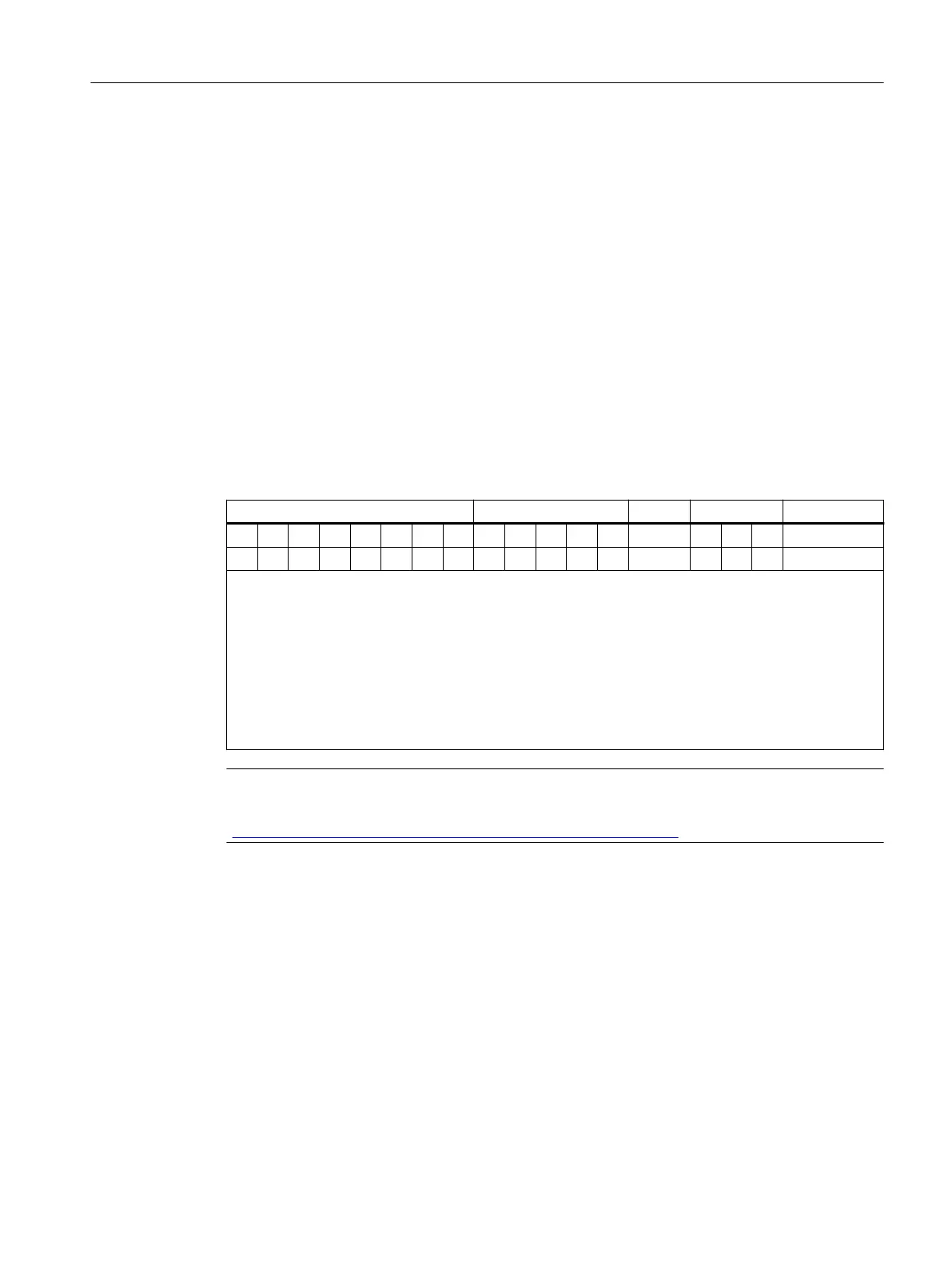
information of the OB40 in the tag OB40_POINT_ADDR. The following table shows the
assignment to the bits of the local data double word 8.
Table 7-26 Interrupts from analog input modules
LB 8 LB 9 LB 10 LB 11
31 30 29 28 27 26 25 24 ... 19 18 17 16 ... ... 1 0 Bit no. LD 8
1 1 1 1 1 1 1 1 ... ...
Bit no. 16: Violation of the low limit channel 0
Bit no. 17: Violation of the low limit channel 1
Bit no. 18: Violation of the low limit channel 2
Bit no. 19: Violation of the low limit channel 3
Bit no. 24: Violation of the high limit channel 0
Bit no. 25: Violation of the high limit channel 1
Bit no. 26: Violation of the high limit channel 2
Bit no. 27: Violation of the high limit channel 3
Note
A description of the OB40 can be found in the reference manual System and standard functions
(https://support.automation.siemens.com/WW/view/en/1214574).
Triggering of a remove/insert interrupt
If you use only DPV0 mode, no interrupts are supported.
The CPU (S7-400) interrupts the processing of the user program and processes the diagnostic
block OB83. The event which led to the triggering of the interrupt is entered in the start
information of the OB83.
Triggering of an Update Interrupt
Update interrupts are only supported in DPV1 operation.
Commissioning and Diagnostics
7.13 Diagnostics with STEP 7 with PROFIBUS
ET 200iSP
Operating Instructions, 11/2022, A5E00247483-AK 201