Interrupts
The interrupt part for ET 200iSP is congured as follows:
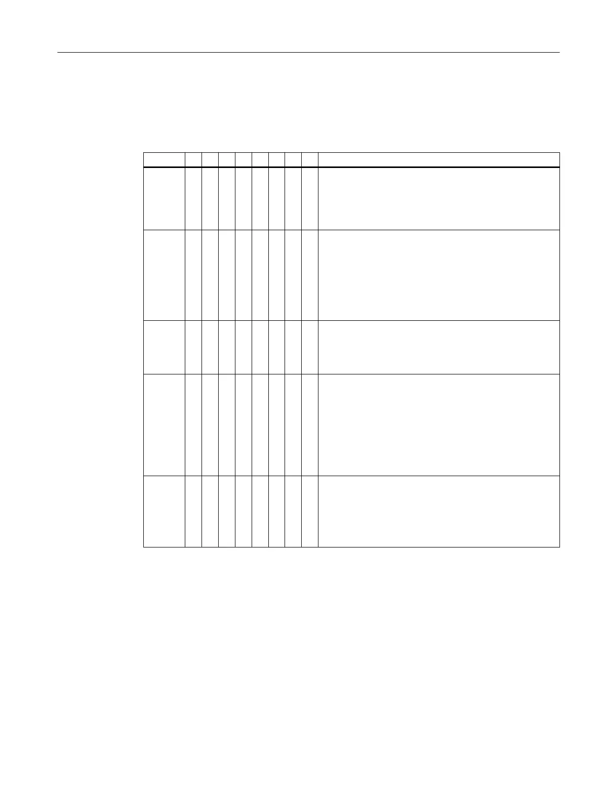
Table 7-39 Structure of the interrupt status of the interrupt section
Byte 7 6 5 4 3 2 1 0 Description
Byte x 0 0 Bit 0 to 5: Length of the interrupt part including byte x (=
max. 48 bytes)
Bit 6 and Bit 7: Code for interrupt diagnostics (for 10
B
, see
section "Channel-related diagnostics with PROFIBUS
(Page 207)")
Byte x+1 0 Bit 0 to Bit 6: Interrupt type:
• 0000001
B
: Diagnostic interrupt
• 0000010
B
: Hardware interrupt
• 0000011
B
: Pull interrupt
• 0000100
B
: Plug interrupt
• 0000110
B
: Update interrupt
Byte x+2 Bit 0 to bit 7: Slot address
02: IM 152-1DP supplies interrupt (diagnostic interrupt,
hardware interrupt for time stamping)
04 to 35: Slot of the module that supplies interrupt
Byte x+3 Bit 0 and Bit 1:
• 00
B
: Hardware interrupt, pull/plug interrupt or update
interrupt
• 01
B
: At least one error is present
• 10
B
: Outgoing error
• 11
B
: Reserved
Bit 3 to bit 7: Interrupt sequence number (1 to 31)
Byte x+4 See diagnostic interrupt, byte x+4 to x+7
See hardware interrupt for analog input modules
See time stamping hardware interrupt at slot 2 (IM 152-1DP)
See pull/plug interrupt
See update interrupt
Diagnostic interrupt, byte x+4 to x+7
Bytes x+4 to x+7 correspond to diagnostic data record 0 in STEP 7.
Commissioning and Diagnostics
7.13 Diagnostics with STEP 7 with PROFIBUS
ET 200iSP
Operating Instructions, 11/2022, A5E00247483-AK 213