Pin assignment
Table 10-5 Pin assignment on the TM‑IM/IM
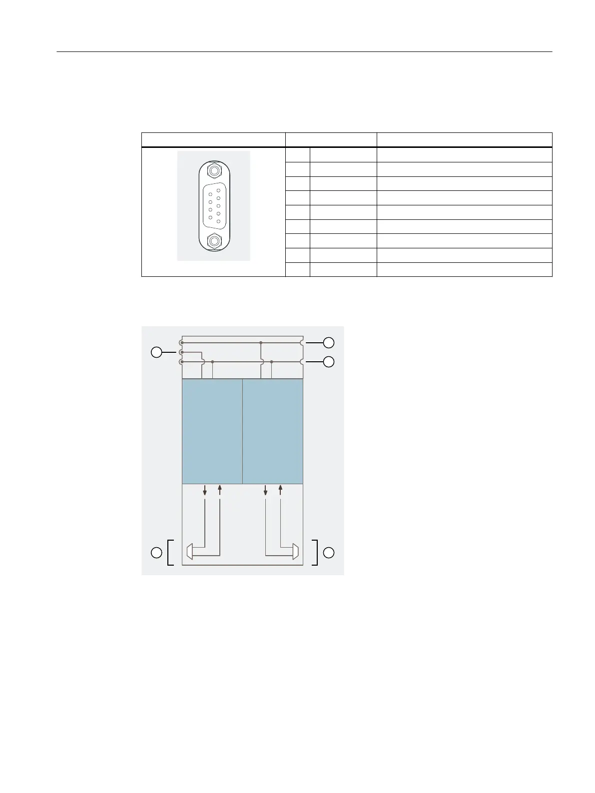
View Terminal Designation
1 PA Equipotential bonding
2 - -
3 RxD/TxD-P Data line B
4 - -
5 ISGND Bus termination ground
6 ISP Bus termination P
7 - -
8 RxD/TxD-N Data line A
9 -
Block diagram
① IM 152-1DP supply
② Power bus
③ Backplane bus
④ PROFIBUS RS 485-IS connection (b)
⑤ PROFIBUS RS 485-IS connection (a)
Figure 10-3 Block diagram of terminal module TM‑IM/IM
Terminal modules
10.4 Terminal module TM-IM/IM
ET 200iSP
Operating Instructions, 11/2022, A5E00247483-AK 259