Setting parameters for the reference junction
You set the reference junctions for the electronic modules 4 AI TC using the following
parameters:
Table 14-30 Reference junction parameters
Parameter Module Range of values Explanation
Slot reference junction 1 to slot 2 Interface mod‐
ule
IM 152-1PN: none, 2 to 33
IM 152-1DP: none, 4 to 35
With this parameter, you can assign up to 2
slots on which the channels for comparison
temperature measurement (determination
of the compensation value) are located.
Input for reference junction (ref‐
erence junction E0 to E3)
Interface mod‐
ule
RTD on channel 0
RTD on channel 1
RTD on channel 2
RTD on channel 3
With this parameter you specify the channel
(0/1/2/3) for comparison temperature meas‐
urement (measurement of the compensa‐
tion value) for the assigned slot.
Reference junction (E0 to E3) 4 AI TC None
Yes
This parameter allows you to enable the use
of the reference junction.
Reference junction number 4 AI TC 1
2
Internal
This parameter allows you to assign the ref‐
erence junction (1, 2) that contains the ref‐
erence temperature (compensation value).
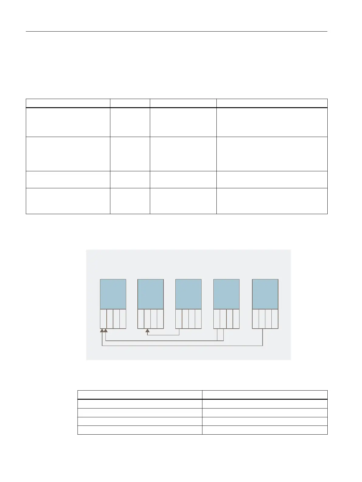
Example of reference junction parameter assignments
• Conguration: For simplication purposes, this gure shows only RTD and TC modules:
$PNQFOTBUJPOWJB"*35%NPEVMFT
3FGFSFODF
KVODUJPO
3FGFSFODF
KVODUJPO
"*5$
&
&
&
&
"*35%
&
&
&
&
"*35%
&
&
&
&
"*5$
&
&
&
&
"*5$
&
&
&
&
Figure 14-7 Example of reference junction parameter assignments
• (Relevant) parameters to be set for the interface module
Parameter Value
Slot reference junction 1 8
Input reference junction 1 RTD on channel 0
Slot reference junction 2 11
Input reference junction 2 RTD on channel 1
Analog electronic modules
14.9 Fundamentals of analog value processing
ET 200iSP
388 Operating Instructions, 11/2022, A5E00247483-AK