Assignment of the process image outputs (PIQ)
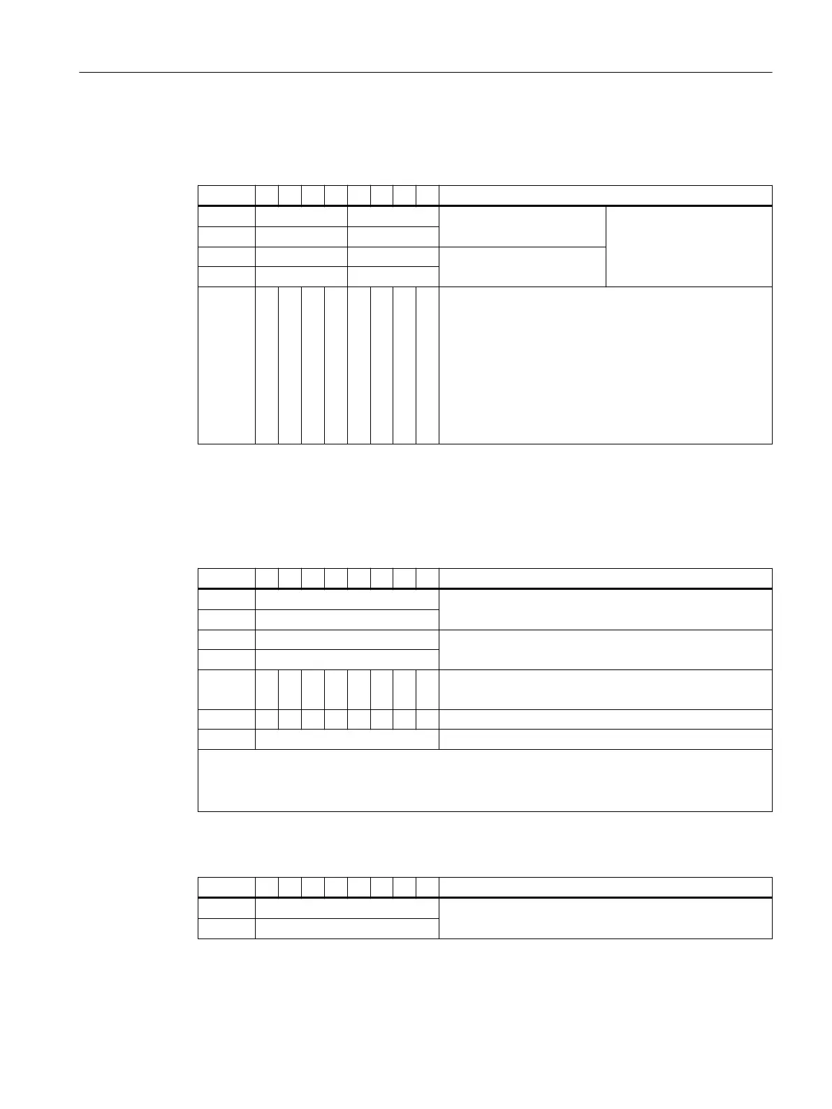
Table A-17 PIQ for conguration "2 Count/ 6 DI NAMUR"
PIQ 7 6 5 4 3 2 1 0 Description
QB x Setpoint counter 1 Setpoint counter 1 (cascad‐
ing counter function)
QB x+1
QB x+2 Setpoint counter 2
QB x+3
QB x+4 Bit 0: Not occupied
Bit 1: Not occupied
Bit 2: Control signal GATE 1
Bit 3: Control signal GATE 2
Bit 4: Control signal reset counter 1
Bit 5: Control signal reset counter 2
Bit 6: Control signal reset counter output 1
Bit 7: Control signal reset counter output 2
8 DI NAMUR mit conguration "2 Trace/ 6 DI NAMUR"
Assignment of the process image inputs (PII)
Table A-18 PII for conguration "2 Trace/ 6 DI NAMUR" (S7 format)
PII 7 6 5 4 3 2 1 0 Description
IB x Frequency meter 1
IB x+1
IB x+2 Frequency meter 2
IB x+3:
IB x+4 Bit 0 and Bit 1: Not occupied
Bit 2 to Bit 7: Digital input 2 to digital input 7
IB x+5 7 6 5 4 3 2
IB x+6 Not occupied
Value status for channels 2 to 7:
• 1
B
: Input signal is valid
• 0
B
: Input signal is invalid
Table A-19 Example: Frequency meter 1 (S7 format)
PII 7 6 5 4 3 2 1 0 Description
IB x 09
H
2317 Hz = 2,317 kHz
IB x+1 0D
H
Assignment of the process image outputs (PIQ)
The PIQ is not assigned.
Appendix
A.4 Address space of the inputs and outputs
ET 200iSP
Operating Instructions, 11/2022, A5E00247483-AK 437