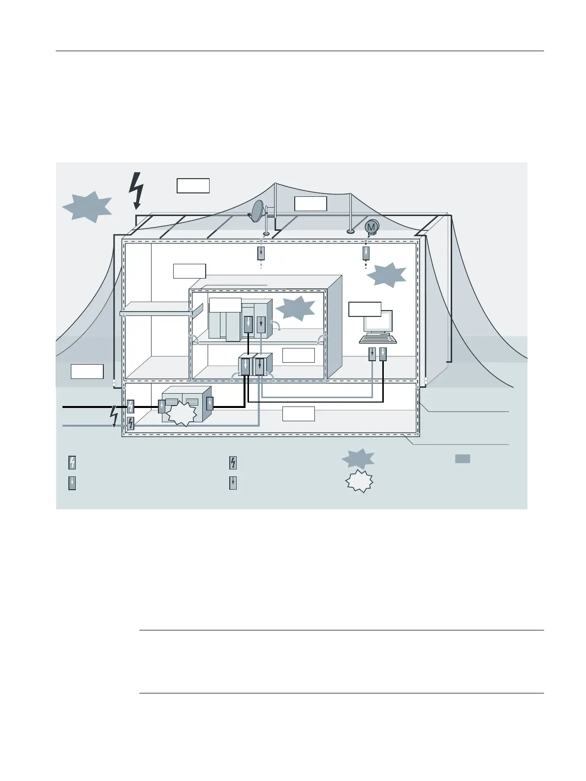
Schematic of lightning protection zones
The following gure shows in schematic form the implementation of the lightning protection
zone concept for a plant with external lightning protection. The lightning protection zone 0
shown in the gure is divided into lightning protection zone 0
A
and 0
B
according to the following
denitions.
-1;
"JSUFSNJOBUJPOTZTUFN
7FOUJMBUJ
%JTDIBSHF
3PPNTIJFME
5FSNJOBMEFWJDF
$PODSFUFGPPUJOHHSPVOEFMFDUSPEF
4UFFMSFJOGPSDFNFOU
-PXWPMUBHF
4VQQMZTZTUFN
*OGPSNBUJPO
UFDIOPMPHZTZTUFN
-JHIUOJOHQSPUFDUJPOFRVJQPUFOUJBM
CPOEJOHMJHIUOJOHBSSFTUFS41%UZQF
-PDBMFRVJQPUFOUJBMCPOEJOHPWFSWPMUBHF
BSSFTUFS41%UZQF41%UZQF
-JHIUOJOHQSPUFDUJPO
FRVJQPUFOUJBMCPOEJOHMJHIUOJOH
BSSFTUFS
-PDBMFRVJQPUFOUJBMCPOEJOH
PWFSWPMUBHFBSSFTUFS
&MFDUSPNBHOFUJD
MJHIUOJOHQVMTF
&MFDUSPNBHOFUJD
MJHIUOJOHQVMTF
-JHIUOJOH
QSPUFDUJPO[POF
4PVSDF
-&.1
-&.1
-&.1
-1;
"
-1;
#
-1;
#
-1;
-1;
-1;
-1;
-1;4&.1
4&.1
-&.1
%&)/4)/&
Figure A-11 Lightning protection zones of a plant with external lightning protection
Principle of interfaces between lightning protection zones
At the interfaces between the lightning protection zones, measures must be taken which have
a reducing eect on the surge current load and on the magnetic elds.
Each zone-penetrating metallic/electrical system must be included in the equipotential bonding
located at the zone transition.
Note
Metal systems include ducts, structural members, pipes (e.g., water, gas, and heat), etc.
Electrical systems include power and information technology cables and lines (e.g. mains
voltage, bus line).
Appendix
A.5 Lightning and overvoltage protection
ET 200iSP
Operating Instructions, 11/2022, A5E00247483-AK 445