Requirements
• The synchronization interval must be set to 20 ms for the master and for the ET 200iSP.
• For time stamping you need the electronic module 8 DI NAMUR with the conguration
"8 DI NAMUR". Time stamping is not possible with all other congurations of the electronic
module 8 DI NAMUR.
How time stamping works
In a system, you can monitor digital inputs for signal changes using conguration in HW Cong.
The following are monitored: "Incoming/outgoing signal" (as "rising or falling edge"). The
interface module stamps these changed input signals with the current time (time stamping) and
stores them as message lists. A message list is a data record with a maximum of 20 messages
about time-stamped signal changes. The interface module can store up to 15 data records.
After a certain time and if there are messages or if a data record is full, the interface module
triggers a hardware interrupt at the CPU (IO controller/DP master). The CPU then reads the data
record and forwards the message lists to an OS using the driver block FB 90 "IM_DRV".
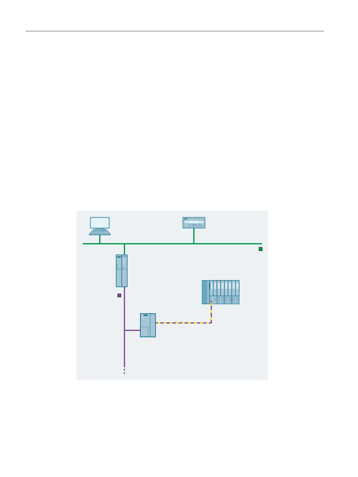
Time stamping example
34*4DPVQMFS
%JHJUBMJOQVUT
"VUPNBUJPOTZTUFN
QMBOUWJTVBMJ[BUJPO
*OEVTUSJBM&UIFSOFU
5JNFPGEBZTFOEFS
&5J41
4
8JO$$
0QFSBUPS4UBUJPO04
4*$-0$,
130'*#64%1
Figure 4-8 Example for time stamping and edge evaluation
Congurations (principle)
4.16 Time stamping
ET 200iSP
90 Operating Instructions, 11/2022, A5E00247483-AK