Wiring
6.6 Wiring rules
Distributed I/O system
System Manual, 09/2019, A5E03576849-AJ
99
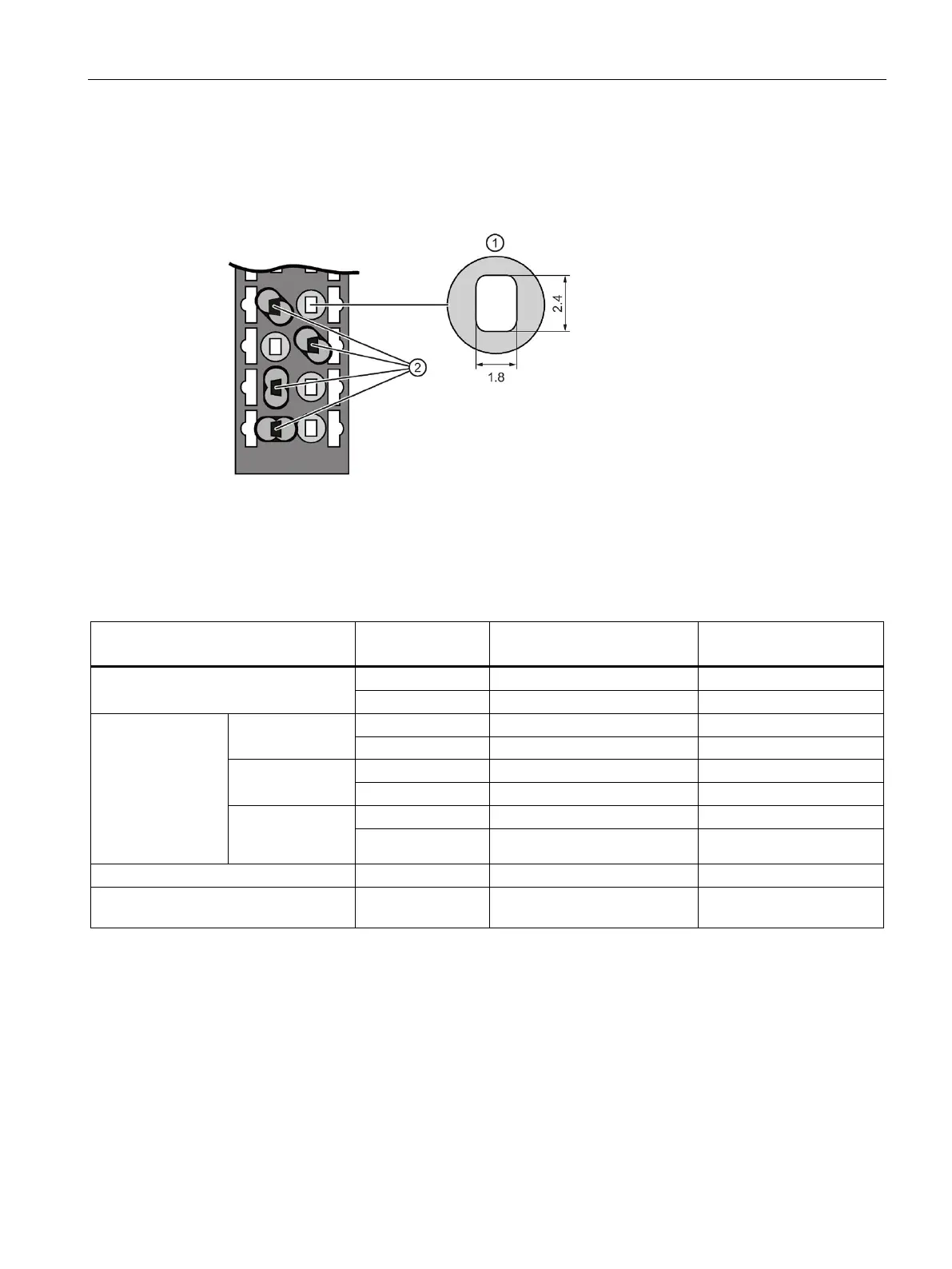
TWIN end sleeves for the cables of the I/O modules' push-in terminals
Due to the space required by TWIN end sleeves with 0.75 mm
2
cross-section, you must
ensure a correct angle for the cable arrangement when crimping the TWIN end sleeve so
that the cables are optimally arranged.
Cross-section of the terminal compartment
Crimping TWIN end sleeves at the correct angle
Figure 6-4 TWIN end sleeves
Wiring rules for motor starters
T1, T2, T3, PE, 24 V DC, F-DI,
M
DI1 ... DI3, LC, M, 24 V
OUT
Permitted cable cross-sections of solid
cables (Cu)
2
2
2
Permitted cable
cross-sections of
flexible cables (Cu)
Without end
sleeve
2
2
2
With end sleeve
2
2
2
AWG: 18 to 10 AWG: 20 to 12 AWG: 24 to 16
With end sleeve
(with plastic
2
2
2
AWG: 18 to 11 AWG: 20 to 16 AWG: 24 to 18
Stripping length of the wires
End sleeves according to DIN 46228
15 mm long 10 mm long 8 mm long
Safety standards for fail-safe motor starters
Fail-safe motor starters fulfill the following standards under certain conditions:
● PL e/Cat. 4 according to EN ISO 13849-1
● Safety Integrity Level SILCL3 acc. to IEC 62061
To fulfill both standards, lay cross-circuit proof and P-cross-circuit proof control cables from
the safe output of a sensor or F-DQ to the safe input of the motor starter, e.g. as a
separately sheathed cable or in a separate cable duct.

 Loading...


