Application planning
4.4 Hardware configuration
Distributed I/O system
System Manual, 09/2019, A5E03576849-AJ
47
4.4 Hardware configuration
Maximum mechanical configuration
As soon as one of the following rules applies, the maximum configuration of the ET 200SP
has been reached:
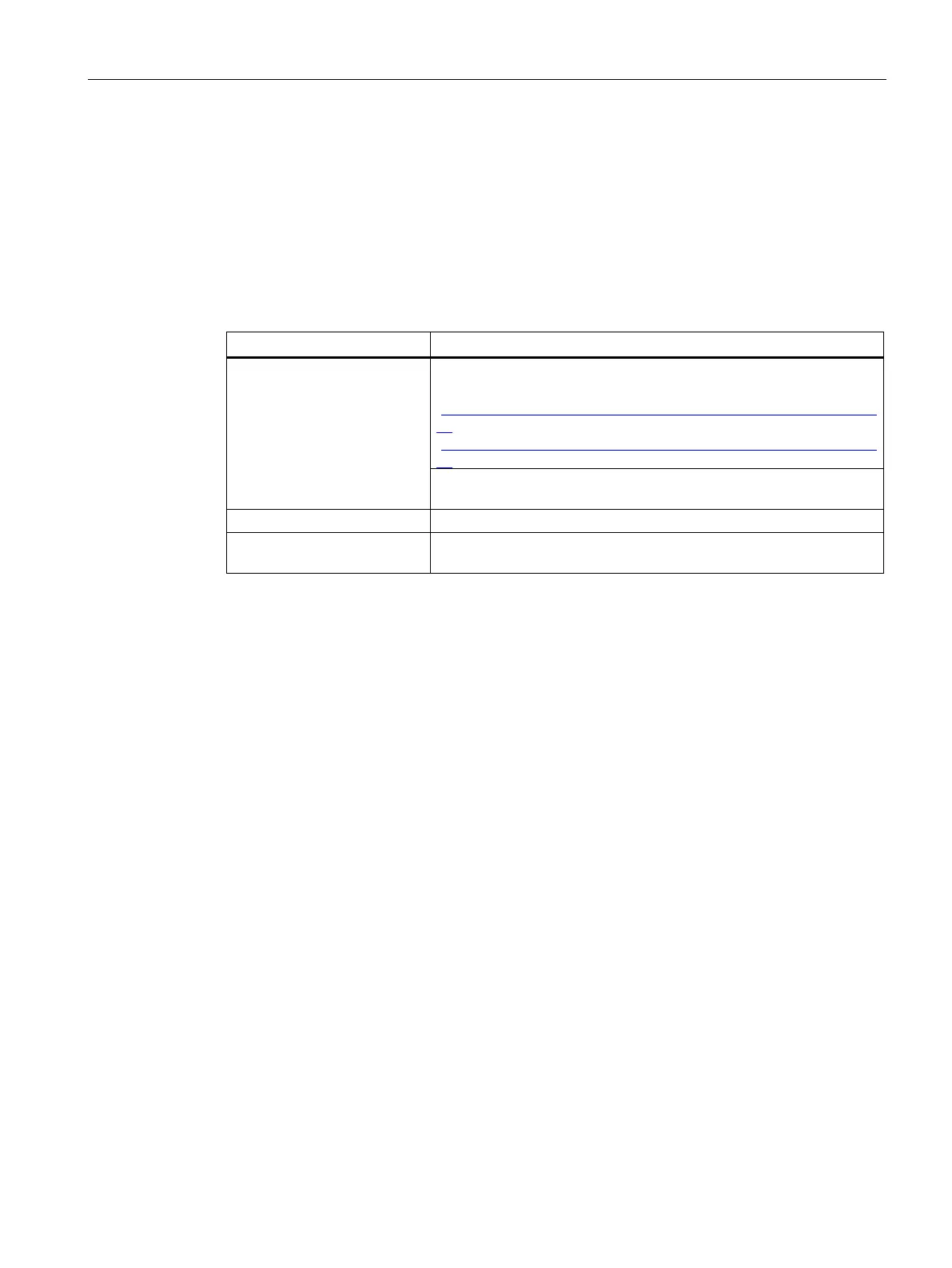
Table 4- 4 Maximum mechanical configuration
Number of modules Maximum of 12/30/32/64 I/O modules (depending on the CPU
used/the interface module used; see CPU
(http://support.automation.siemens.com/WW/view/en/90466439/1333
00) and interface module
(http://support.automation.siemens.com/WW/view/en/55683316/1333
For every 6 F-modules F-RQ 1x24VDC/24..230VAC/5A (6ES7136-
6RA00-0BF0), the maximum configuration is reduced by 1 module.
Maximum of 31 motor starters
Backplane bus length of the
maximum 1 m mounting width (without CPU/interface module, includ-
Electrical maximum configuration for I/O modules
The number of operable I/O modules of a potential group is limited by the following factors:
● Power consumption of the I/O modules
● Power consumption of the components supplied via these I/O modules
The maximum current carrying capacity of the terminals on the BaseUnit L+/M is 10 A.
Current carrying capacity refers to the current load via the power bus and the infeed bus of
the ET 200SP station. Consider the current carrying capacity when using a motor starter.
Maximum electrical configuration for motor starter power bus (24 V DC)
To determine the current requirement of an individual motor starter via the power bus, take
account of the following parameters:
● Current consumption via DC infeed in the ON state
● Current consumption via DC infeed when switching on (40 ms peak load)
● Increased power consumption through fan operation
● Current requirement via encoder supply of the connected DI module
The maximum current carrying capacity of the 24 V potential group is 7 A across the entire
permissible temperature range.

 Loading...


