Wiring
6.7 Wiring BaseUnits for I/O modules
Distributed I/O system
System Manual, 09/2019, A5E03576849-AJ
101
6.7 Wiring BaseUnits for I/O modules
Introduction
The BaseUnits connect the ET 200SP distributed I/O system to the process. The following
versions of the BaseUnits can be used:
● BaseUnits (with light-colored terminal box) for opening a potential group: BU..D
● BaseUnits (with dark-colored terminal box) for extending the potential group: BU..B
● BaseUnits with additional AUX terminals or additional terminals: BU..+10..
● BaseUnits with integrated thermal resistor for compensation of the reference junction
temperature when connecting thermocouples: BU..T
● PotDis-BaseUnits (with light-colored terminal box) for opening a PotDis potential group:
PotDis-BU..D
● PotDis-BaseUnits (with dark-colored terminal box) for extending the potential group:
PotDis-BU..B
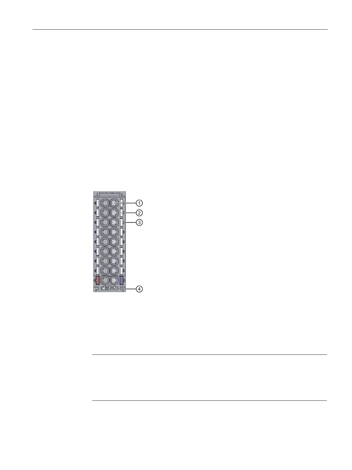
Measuring probe (suitable probes: 1 mm diameter, length ≥ 10 mm while observing the
permitted voltage category)
Holder for shield connection
Figure 6-5 View of the BaseUnit
Note
The pin assignment of the BaseUnit depends on the connected I/O module. Information
on the BaseUnit
s and I/O modules can be found in the associated manuals.
Replacement of the terminal box on the BaseUnit is described in the section
Replacing
the terminal box on the BaseUnit
(Page 240).

 Loading...


