Application planning
4.5 Forming potential groups
Distributed I/O system
56 System Manual, 09/2019, A5E03576849-AJ
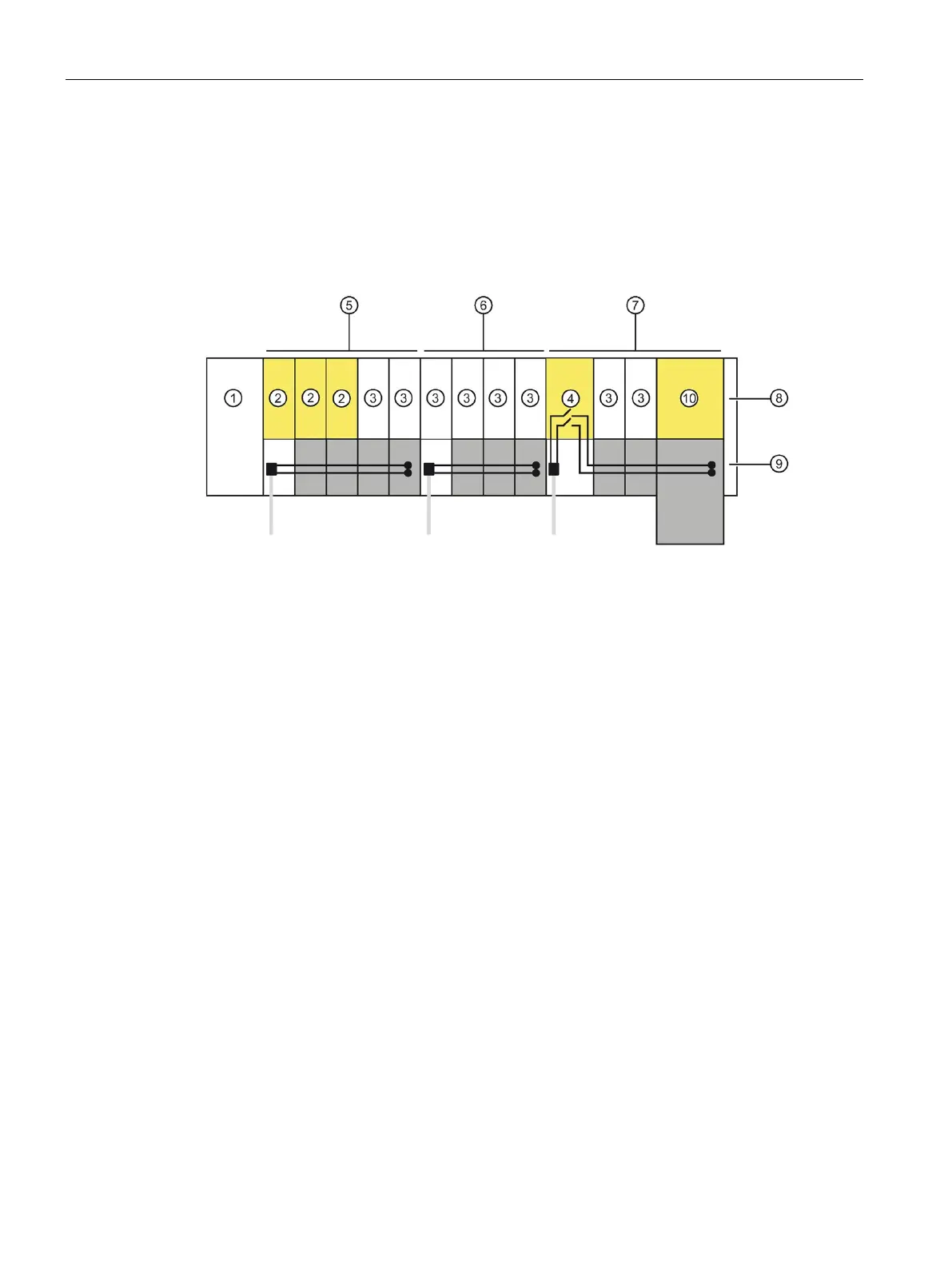
Example of an ET 200SP configuration with fail-safe and non-fail-safe modules
In principle, it is not necessary to operate fail-safe and non-fail-safe modules in separate
potential groups. You can divide the modules into fail-safe and non-fail-safe potential groups
and install them.
The figure below shows an example of a configuration with fail-safe and non-fail-safe
modules within a single ET 200SP distributed I/O system.
IM 155-6 PN HF interface module
Power module F-PM-E 24VDC/8A PPM ST
Mixed fail-safe and non-fail-safe potential group with BaseUnits BU15..D and BU15..B.
You achieve SIL3/Cat. 4/PLe for the fail-safe modules. No safety category can be achieved
with the non-fail-safe motor starter.
Non-fail-safe potential group with BaseUnits BU15..D and BU15..B
Fail-safe potential group with BaseUnits BU20..D, BU15..B and BU30-MSx.
Up to SIL2/Cat. 3/PLd is possible if you disconnect the self-assembling voltage bus and thus
the non-failsafe modules.
Self-assembling voltage buses P1/P2
Fail-safe motor starter F-DS HF
Figure 4-6 ET 200SP - example of a configuration with fail-safe modules

 Loading...


