Product overview
2.2 Components
S7-1500 Automation System
16 System Manual, 01/2013, A5E03461182-01
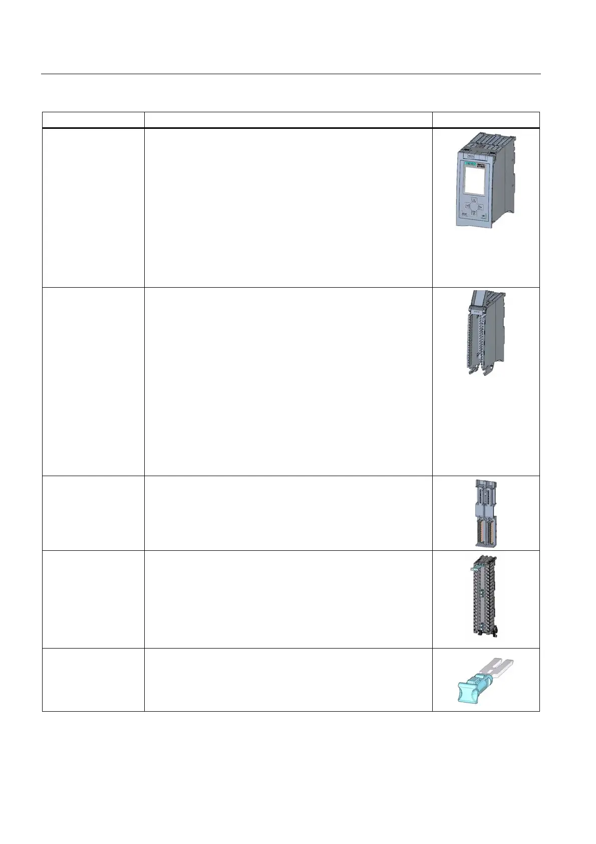
Components Function Diagram
CPU The CPU executes the user program and uses the integrated system
power supply to supply the electronics of the modules via the
backplane bus.
Further features and functions of the CPU:
• Communication via Ethernet
• Communication via PROFIBUS/PROFINET
• HMI communication
• Integrated web server
• Integrated technology
• Integrated system diagnostics
• Integrated security
I/O module The I/O modules form the interface between the controller and the
process. The controller detects the current process state via the
connected sensors and actuators, and triggers the corresponding
reactions. I/O modules are classified into the following types of
modules:
• Digital input (DI)
• Digital output (DQ)
• Analog input (AI)
• Analog output (AQ)
• Technology module (TM)
• Communication module (CM)
• Communication processor (CP)
A U connector is included in the scope of delivery for each
I/O module.
U connector The modules of the S7-1500 automation system are connected using
the U connector. The U connector provides the mechanical and
electrical connection between the modules.
The U connector is included in the scope of delivery of all modules
(exception: CPU) and may be ordered as a spare part (Page 193).
Front connectors The front connector serves for the wiring of the I/O modules.
The front connector for technology and analog modules must be
supplemented with a shielding bracket, power supply element, and
shielding clamp. These components are included in the scope of
delivery of the technology and analog modules, and may be ordered
as accessories (Page 193).
Four potenti
al bridges and one cable tie are included in the scope of
delivery of the front connector.
Potential bridges for
front connector
Two terminals can be bridged with potential bridges.
The potential bridges are included in the scope of delivery of the front
connector, and may be ordered as a spare part (Page 193).

 Loading...


