Wiring
6.7 Connect interfaces for communication
S7-1500 Automation System
System Manual, 01/2013, A5E03461182-01
63
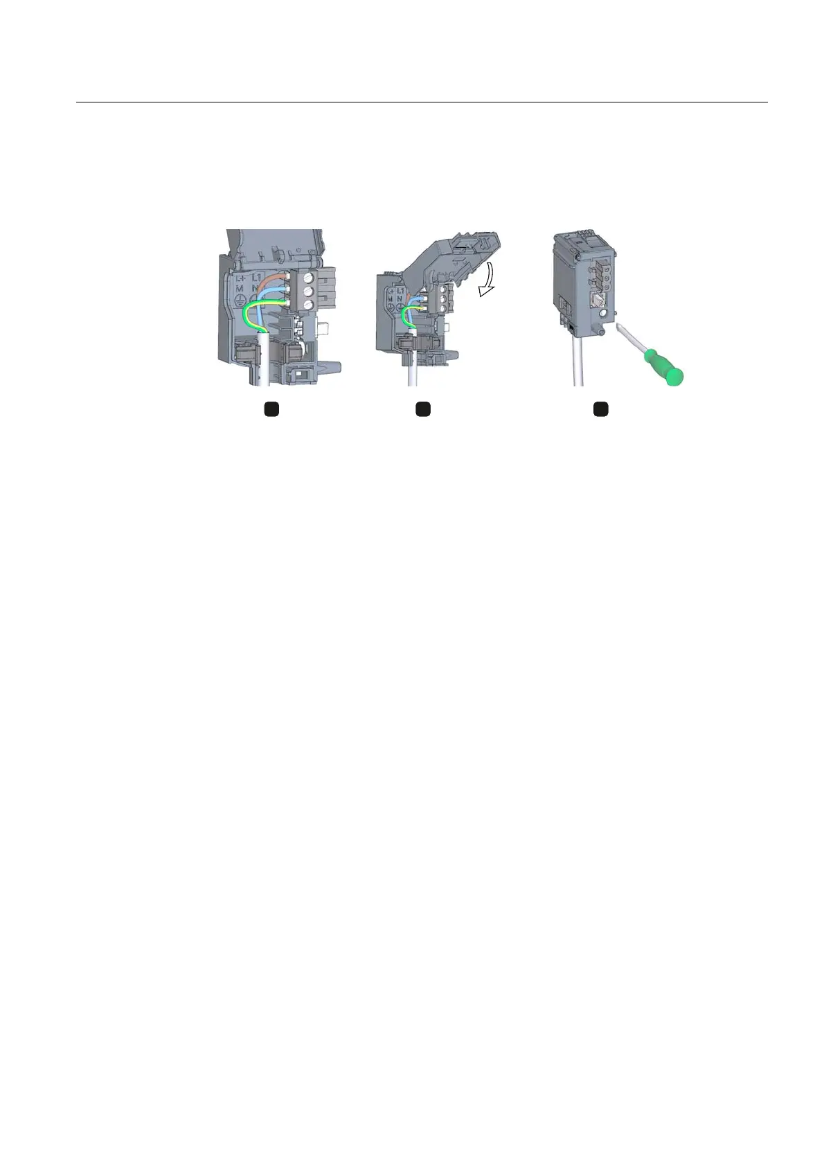
6. Connect the wires in the connector according to the connection diagram (Figure 4).
7. Close the cover (Figure 5).
8. Retighten the screw (Figure 6). This effects a strain relief on the lines.
Figure 6-5 Connecting the supply voltage to the system power supply and load current supply
modules (2)
9. Insert the power connector into the module, until the latch engages.
Reference
Further information about connecting the 24 VDC output voltage of the load voltage supply
modules is available in the Manuals of the corresponding modules.
6.7 Connect interfaces for communication
Communication interfaces of the S7-1500 modules are connected using standardized
connectors.
Use prefabricated connecting cables for the connection. If you want to prepare
communication cables yourself, the interface assignment is specified in the Manuals of the
corresponding modules. Observe the mounting instructions for the connectors.

 Loading...


