S7-1500 Automation System
System Manual, 01/2013, A5E03461182-01
29
Application planning
4
4.1 Hardware configuration
Introduction
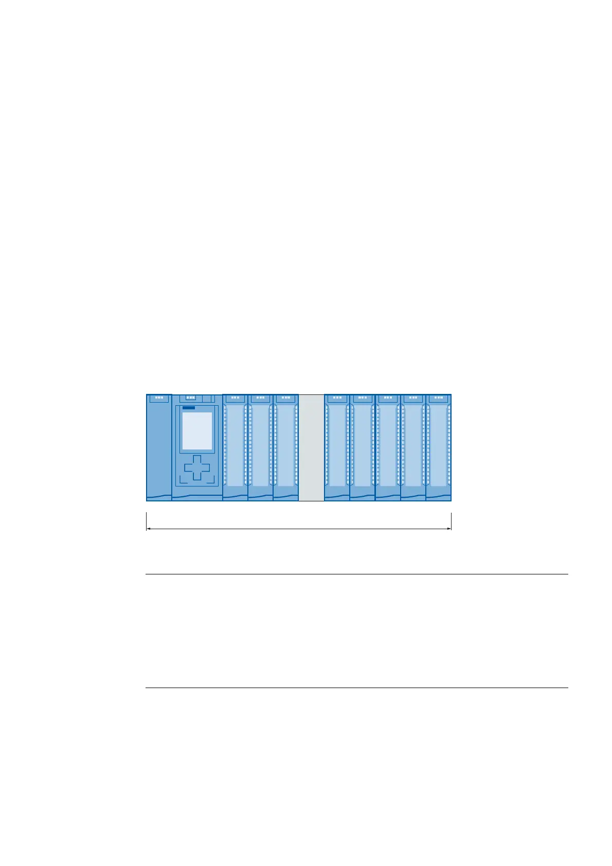
The configuration of an S7-1500 automation system consists of a single-row configuration, in
which all modules are installed on a mounting rail. The modules are connected by means of
U connectors, and thus form a self-assembling backplane bus.
Rule
An S7-1500 automation system consists of a maximum of 32 modules, which occupy slots
0 to 31. The S7-1500 automation system supports a single-row configuration in which all
modules are installed on a mounting rail.
0RGXOH
0D[LPXPRIPRGXOHV
36&38
0RGXOH 0RGXOH0RGXOH 0RGXOH 0RGXOH0RGXOH0RGXOH
RSWLRQDO
6ORWV
Figure 4-1 Configuration of an automation system with up to 32 modules
Note
Placing load current supplies
Load current supplies do not have a connection to the backplane bus of the S7-1500
automation systems and therefore do not use a configurable slot. Load current supplies can
be mounted to the left or right of the configured setup. If you mount a load current supply on
the right of the configured setup, the heat development of the load current supply may make
a gap to the configured setup necessary. For additional information, refer to the relevant
manuals. The number of load current supplies that can be used is unlimited.

 Loading...


