Wiring
6.4 Wiring rules
S7-1500 Automation System
System Manual, 01/2013, A5E03461182-01
59
6.4 Wiring rules
Wiring rules
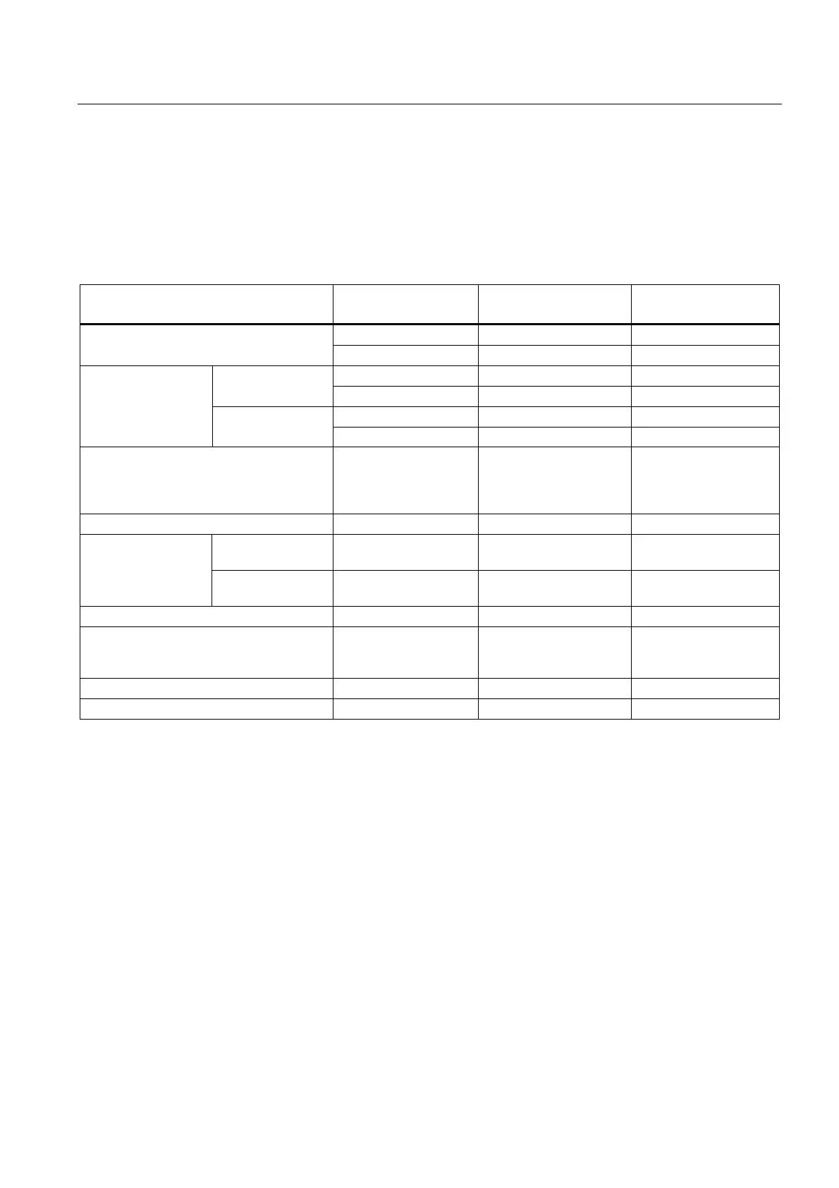
Table 6- 2 Wiring rules
Wiring rules for... CPU 40-pin front connector
(screw-type connection)
System power and load
current supply
- up to 0.25 mm
2
- Connectible conductor cross-sections for
solid wires
- AWG
*:
up to 24 -
0.25 to 1.5 mm
2
0.25 to 1.5 mm
2
1.5 mm
2
Without end sleeve
AWG
*
: 24 to 16 AWG
*
: 24 to 16 AWG
*
: 16
0.25 to 1.5 mm
2
0.25 to 1.5 mm
2
1.5 mm
2
Connectible
conductor cross-
sections for stranded
wires
With end sleeve
AWG
*
: 24 to 16 AWG
*
: 24 to 16 AWG
*
: 16
Number of wires per connection 1 1 or combination of 2
wires up to 1.5 mm
2
(total) in the same end
sleeve
1
Length of stripped wires 10 to 11 mm 10 to 11 mm 7 to 8 mm
without plastic
sleeve
Design A, 10 mm long Design A, 10 mm and
12 mm long
Design A, 7 mm long End sleeves
according to
DIN 46228
with plastic sleeve
0.25 to 1.5 mm
2
Design E, 10 mm long Design E, 10 mm and
12 mm long
Design A, 7 mm long
Sheath diameter - - 8.5 mm
Tool 3 to 3.5 mm
screwdriver, conic
design
3 to 3.5 mm screwdriver,
conic design
3 to 3.5 mm
screwdriver, conic
design
Connection technology Push-in terminal Screw terminal Screw terminal
Tightening torque - from 0.4 Nm to 0.7 Nm from 0.5 Nm to 0.6 Nm
* American Wire Gauge

 Loading...


