Wiring
6.8 Front connector for the I/O modules
S7-1500 Automation System
64 System Manual, 01/2013, A5E03461182-01
6.8 Front connector for the I/O modules
6.8.1 Characteristics of the front connector
Introduction
The sensors and actuators of your plant are connected to the S7-1500 automation system by
means of front connectors. Wire the sensors and actuators to the front connector and then
plug it into the I/O module. Wire the front connector in the "pre-wiring position" that makes
convenient wiring possible before you insert it into the I/O module.
The completely wired front connector can be removed easily from the I/O module and
replaced without a lot of effect when a module is replaced.
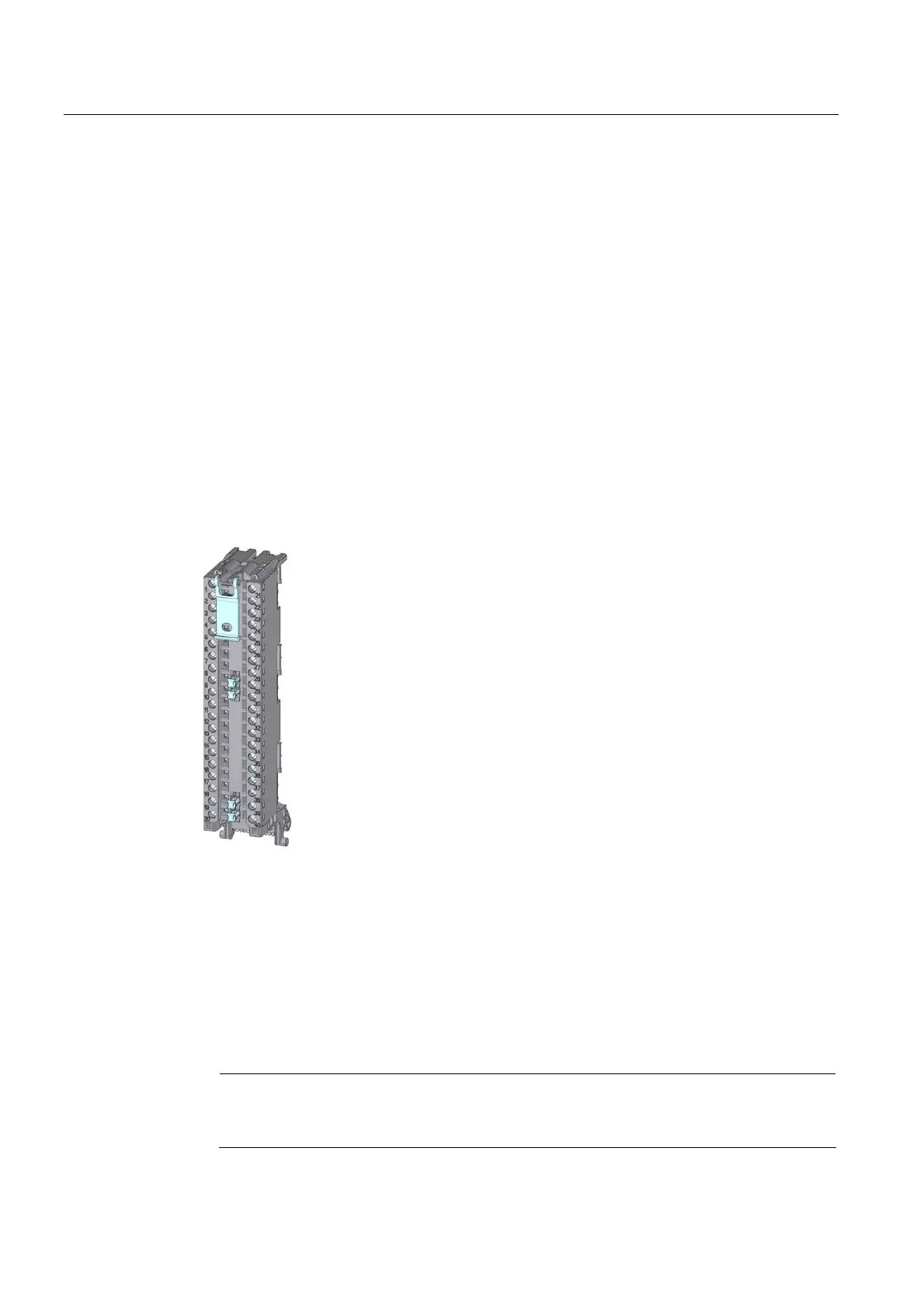
Characteristics of the front connector
Figure 6-6 Front connectors
The front connector is characterized by the following:
● 40 clamping points each
● Clamping technology: Screw
● If you want to supply load groups with the same potential (non-isolated), use the potential
bridges supplied for the front connector. In four locations: 9 and 29, 10 and 30, 19 and
39, 20 and 40, the terminals can be bridged by means of potential bridges. Advantage:
Reduction of the wiring effort.
Note
Note that the potential bridges may only be deployed with a maximum rated voltage of
24 VDC! The current capacity per potential bridge is 8 A maximum.

 Loading...


