Wiring
6.8 Front connector for the I/O modules
S7-1500 Automation System
68 System Manual, 01/2013, A5E03461182-01
6.8.3 Wiring front connectors for I/O modules with shield contact element
Requirements
● I/O modules are installed on the mounting rail.
● The supply voltage is turned off.
● The wires are prepared according to the utilized clamping technology, take the wiring
rule
s (Pag
e 59) into account to this purpos
e.
Tools required
● 3 to 3.5 mm screwdriver
● Flat pliers
Details view
The shielding bracket, the power supply element, and the shielding clamp are included in the
scope of delivery for the analog and technology modules.
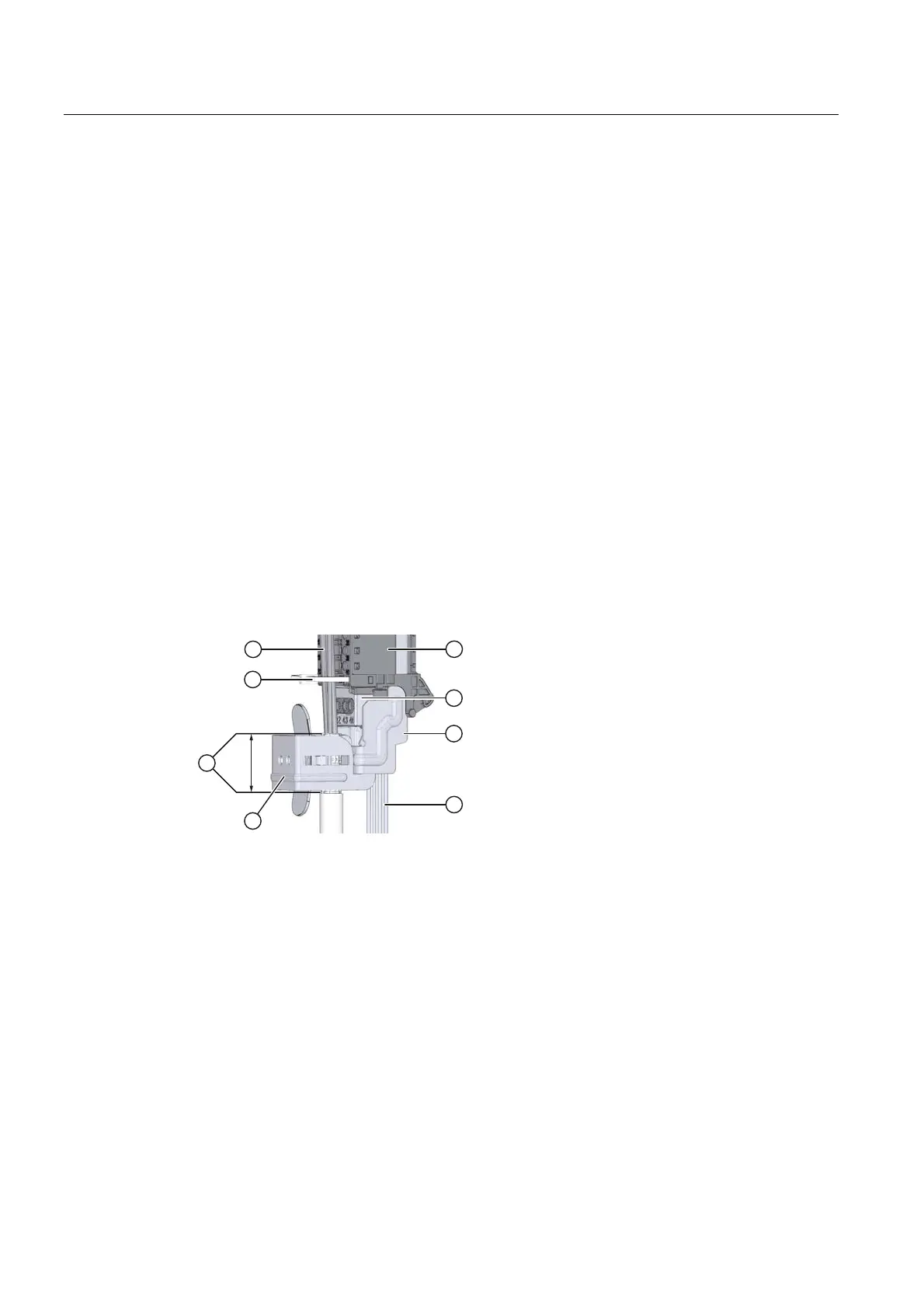
The following figure shows the details view of a front connector with shield connection
element:
① Shield clamp ⑥ Power supply element
② Cable sheathing removed
(approx. 20 mm)
⑦ Shielding bracket
③ Strain relief (cable tie) ⑧ Supply lines
④ Signal cables ①+⑦ Shield contact
⑤ Front connectors
Figure 6-8 Details view for front connectors with shield connection elements

 Loading...


