Wiring
6.6 Connecting the system power supply and load current supply modules
S7-1500 Automation System
62 System Manual, 01/2013, A5E03461182-01
6.6 Connecting the system power supply and load current supply
modules
Introduction
In the delivery state of the system power supply and load current supply modules, power
connectors are inserted. The modules and the associated power connectors are coded. The
coding is effected by means of two coding elements - one coding element is located in the
module, and the other in the power connector. The system power supply and load current
supply modules use identical power connectors for the voltage connection.
The coding element prevents the insertion of a power connector into a different type of
power supply module / load current supply module.
Tools required
3 to 3.5 mm screwdriver
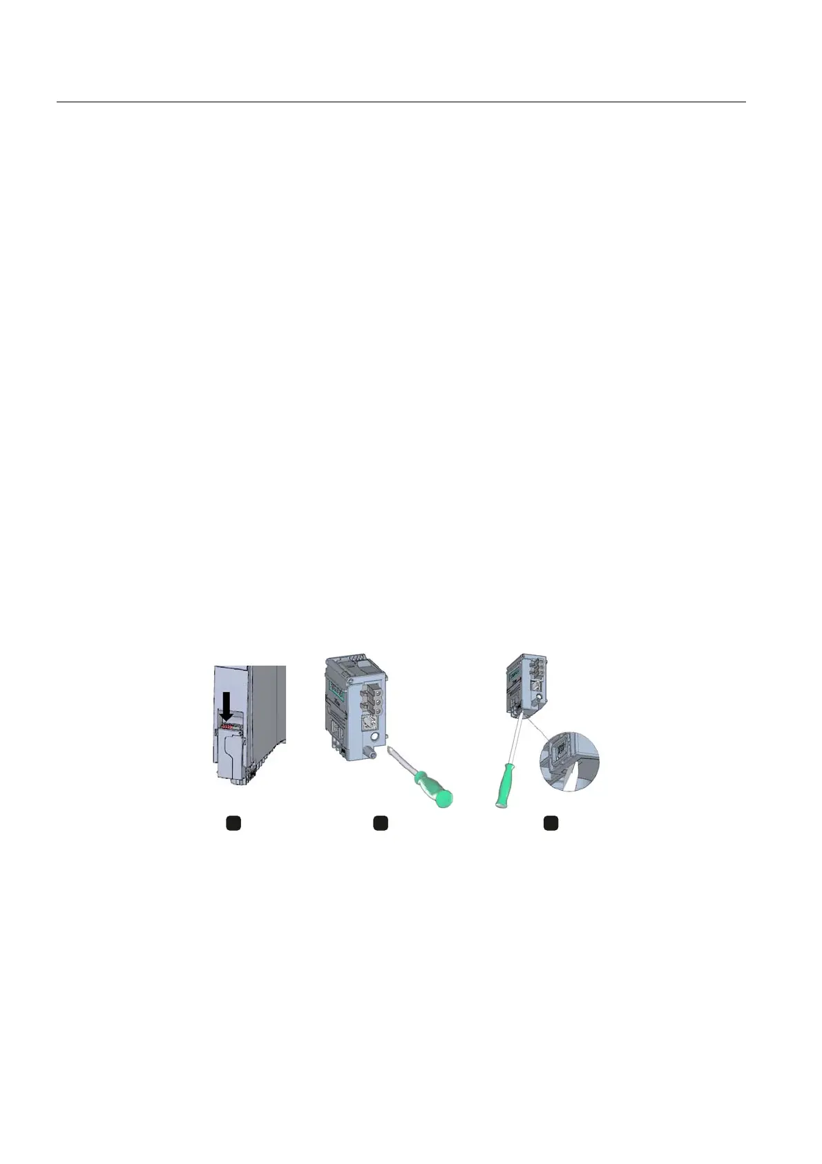
Connecting the supply voltage to the system power supply and load current supply modules
1. Swing the front cover of the module up until the front cover latches.
2. Unlock the power connector and remove it from the module by pulling it forward. For this
purpose, press the unlocking button down (Figure 1).
3. Loosen the screw on the front of the connector. This loosens the housing latch and the
cable relief. With a tightened screw the connector's cover can't be removed (Figure 2).
4. Pry off the connector cover using a suitable tool (Figure 3).
Figure 6-4 Connecting the supply voltage to the system power supply and load current supply
modules (1)
5. Strip the cable sheathing to a length of 35 mm and the conductors to a length of
7 to 8 mm, and bring them up to the end sleeves.

 Loading...


