Application planning
4.2 System and load power supply
S7-1500 Automation System
34 System Manual, 01/2013, A5E03461182-01
Infeed via CPU and system power supply
For larger hardware configurations, infeed into the backplane bus by the CPU alone no
longer suffices. If then modules in total consume more than 10 or 12 W, insert an additional
system power supply.
Supply the system power supply with the permissible supply voltage and the CPU with
24 VDC from a load current supply.
Both the system power supply and the CPU feed current into the backplane bus. The
supplied power is summed.
Power addition: "System power supply infeed power" + "CPU infeed power"
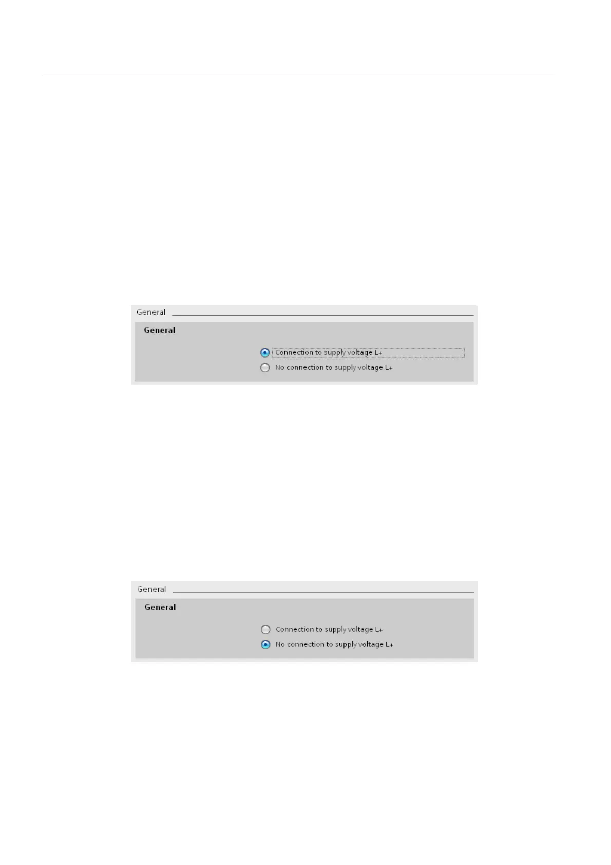
Parameter assignment of the CPU: Select the "Connection to supply voltage L+" option in
STEP 7 in the "Properties" tab in the "System power supply" area navigation so that the
power balance of STEP 7 can be calculated correctly.
Figure 4-5 Supply voltage via the CPU and system power supply
Infeed via system power supply only
As a further possibility you can feed the required power into the backplane bus using only a
system power supply. In this case, the CPU is not supplied with 24 VDC, and draws its
supply from the backplane bus. Insert the system power supply next to the CPU, on the left.
In general you can use system power supplies with AC or DC infeed for the configuration. If
the first power segment is to be supplied directly with 230 VAC, an infeed via only one
system power supply makes sense, for example if no 24 VDC supply voltage is available.
Parameter assignment of the CPU: Select the "No connection to supply voltage L+" option in
STEP 7 in the "Properties" tab in the "System power supply" area navigation so that the
power balance of STEP 7 can be calculated correctly.
Figure 4-6 No infeed into the backplane bus through the CPU

 Loading...


