Installation
5.1 Basics
S7-1500 Automation System
40 System Manual, 01/2013, A5E03461182-01
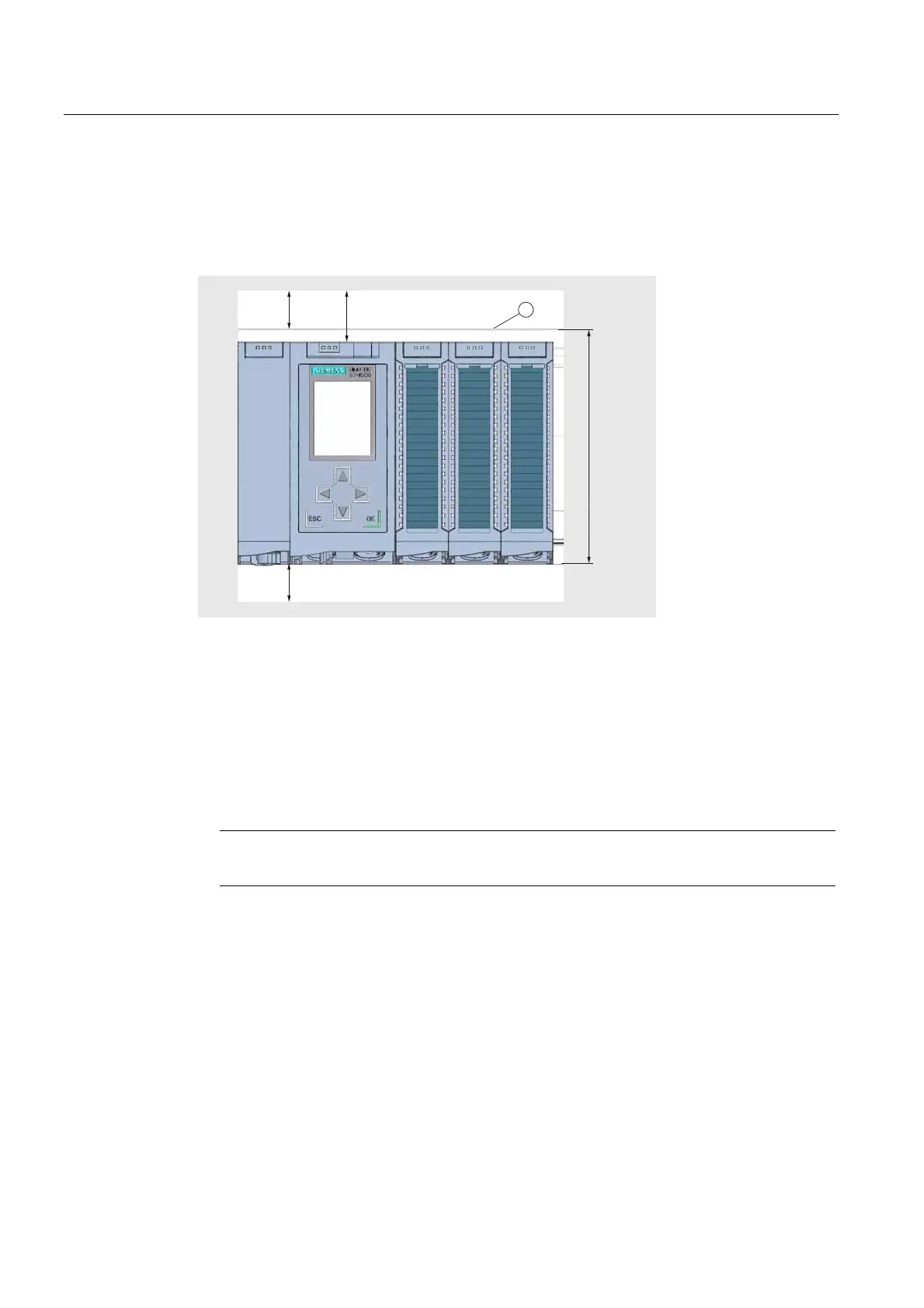
Minimum clearances
Modules can be mounted up to the outer edge of the mounting rail. Maintain the following
minimum clearances at the top and bottom when installing or removing the S7-1500
automation system.
1
PP
PP
PP
PP
① Upper edge of the mounting rail
Figure 5-1 Minimum clearances in the control cabinet
Installation rules
● The installation begins on the left side with a CPU, or a power supply module.
● The modules are connected to each other with U connectors.
● Note that no U connector protrudes from the first and last module.
Note
Only insert modules when the power is switched off.

 Loading...


