Configuring
7.1 Address assignment
S7-1500 Automation System
86 System Manual, 01/2013, A5E03461182-01
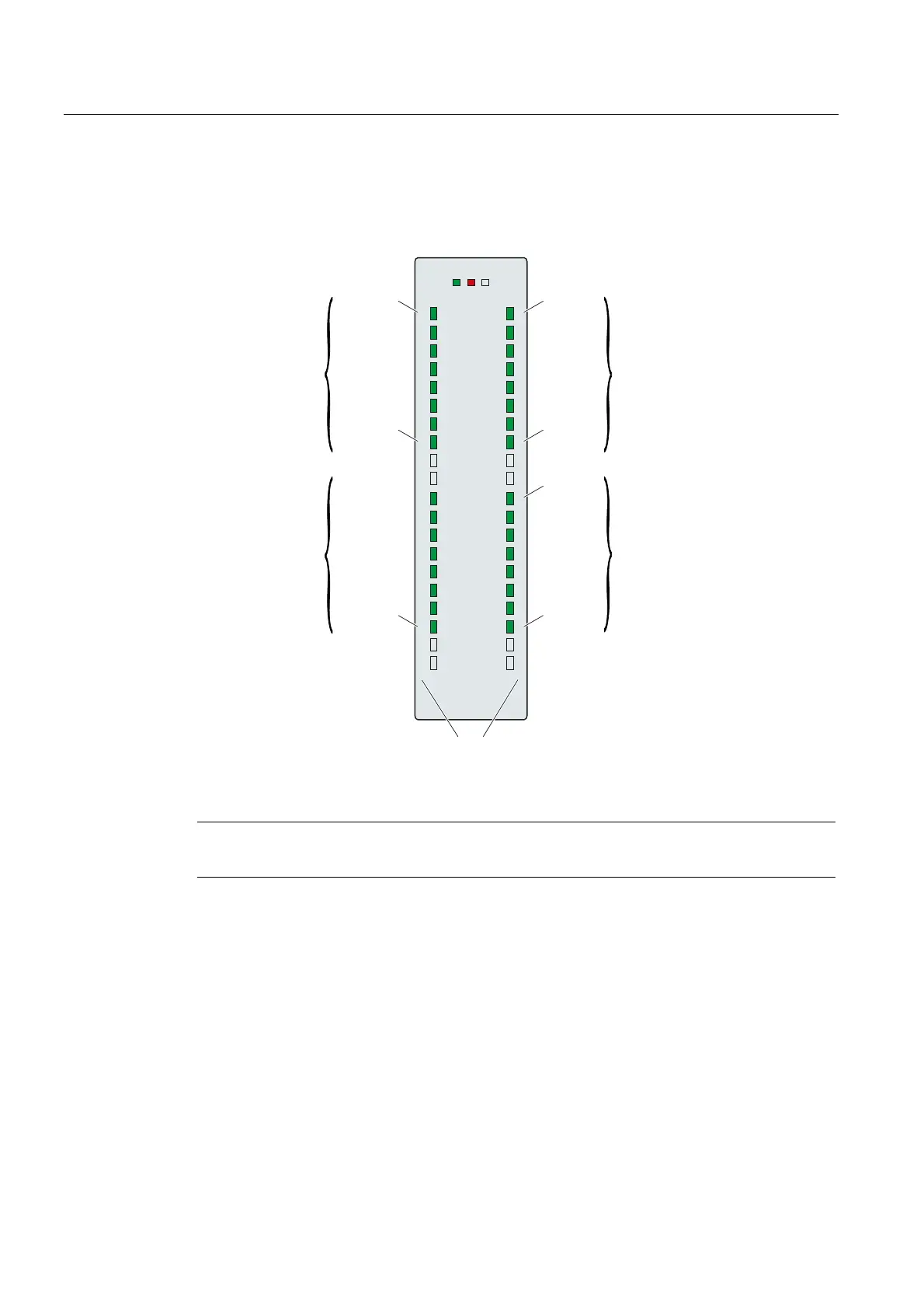
Example for the assignment of channel addresses (digital module)
The following figure shows how the addresses of the individual channels of the digital input
module (e.g., 6ES7521-1BL00-0AB0) are determined.
%\WHDGGUHVV
&+
&+
&+
&+
D
3
E
3
F
G
3
&+
&+
&+
&+
3
%\WDGUHVVH
0RGXO$QIDQJVDGUHVVH
%\WDGUHVVH
0RGXO$QIDQJVDGUHVVH
%\WDGUHVVH
0RGXO$QIDQJVDGUHVVH
%\WDGUHVVH
0RGXO$QIDQJVDGUHVVH
$GUHVVHD
$GUHVVHD
$GUHVVHE
$GUHVVHE
$GUHVVHF
$GUHVVHF
$GUHVVHG
$GUHVVHG
Figure 7-8 Example for the assignment of channel addresses (digital module)
Note
You can also assign symbolic names to the addresses in STEP 7's PLC tag table.
Reference
Additional information on addressing and address allocation with value status can be found
in the manuals of the digital modules, and in the online help for STEP 7.

 Loading...


