[logik-synchrocheckfunktion-110403-kn, 1, en_GB]
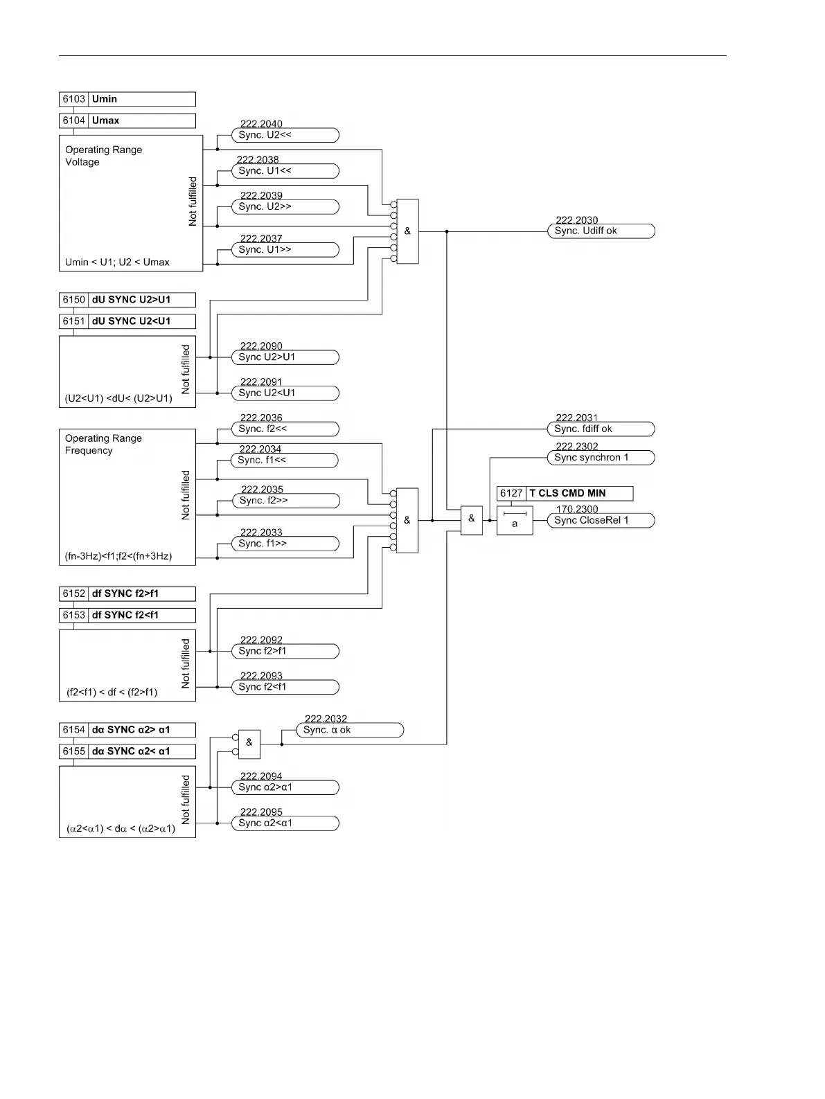
Figure 2-9
Logic diagram of the synchronization function (illustration for one channel)
If the corresponding conditions are fulfilled the indications
Sync. Udiff ok
,
Sync. fdiff ok
, and
Sync. α ok
are issued.
The indications in the left part of the logic diagram describe if general conditions are fulfilled or not. This indi-
cation category will be explained using two examples. The indiciation
Sync. U2<<
shows that the voltage U2
is outside the operating range and is smaller than the set minimum threshold. The indiciation
Sync U2<U1
is
produced if the difference voltage is outside the setting limits. Here the lower setting value 6151 dU SYNC
U2<U1 is not reached. This indication contains indirect information that voltage U2 must unconditionally be
Functions
2.2 Paralleling Functions
44 SIPROTEC 4, 7VE61 and 7VE63, Manual
C53000-G1176-C163-3, Edition 10.2017

 Loading...


