changes, the next actuator command is issued only after this response time has expired. This time can be like-
wise parametrized as T U PAUSE or T f PAUSE.
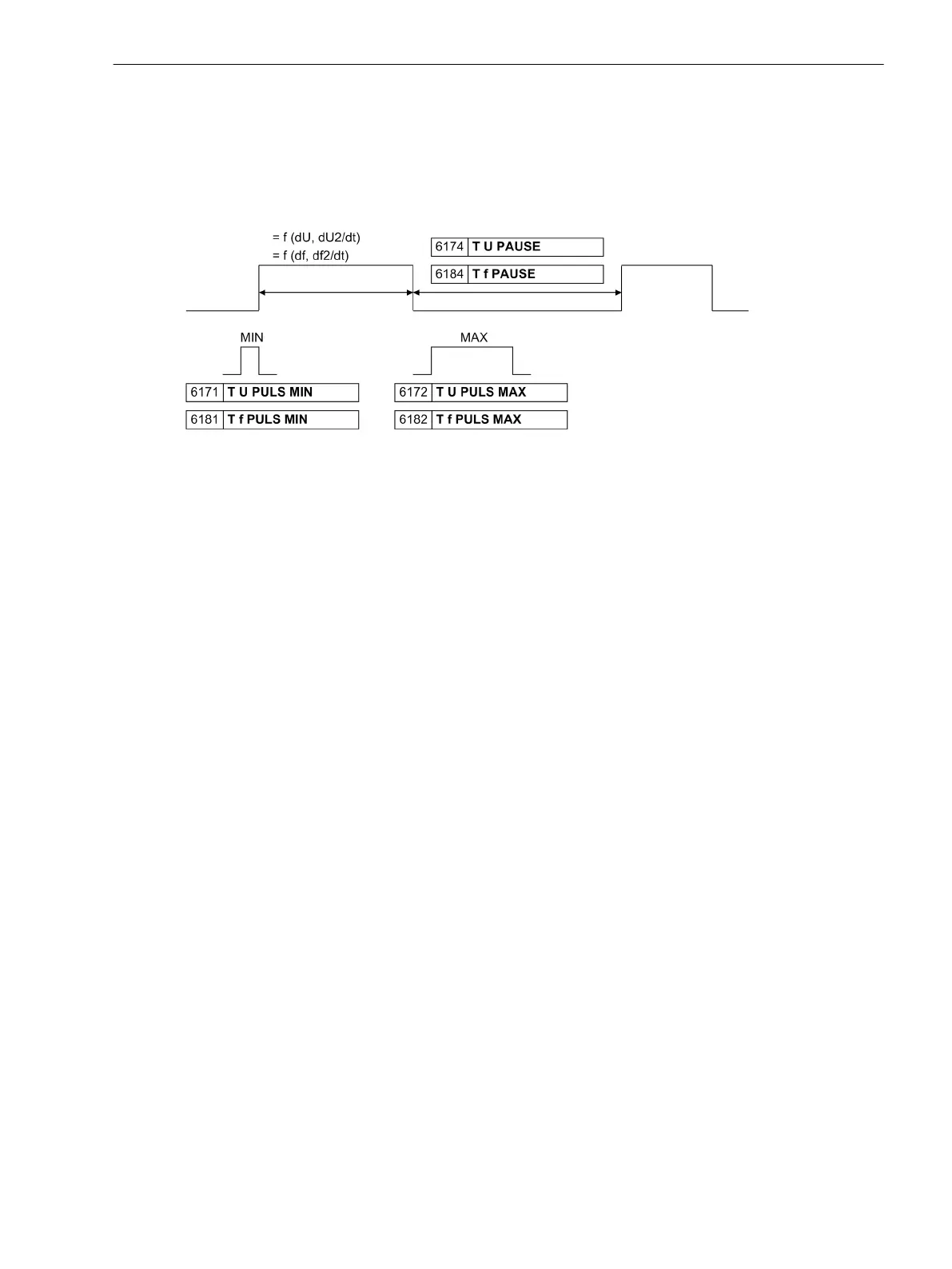
The main effect of the times is shown in Figure 2-19. The actuator time depends on the measured difference
values (dU or df) and on the set control speed (dU/dt or df/dt). For larger actuator times a restriction results
from the maximum pulse length. If the actuator time is larger, it is distributed among several pulses. Calcu-
lated actuator times less than the required minimum pulse time are output.
[stell-und-pausenzeichen-240403-oz, 1, en_GB]
Figure 2-19 Actuator and pause
Voltage Balancing
The amplitude of side 2 can be adjusted using actuator pulses via the voltage controller or the transformer tap
changer. The permissible range for the synchronization is defined by parameters 6130 dU ASYN U2>U1 and
6131 dU ASYN U2<U1. The mean value of the two setting parameters is used as a target value for deriving
the setting pulse. In case of very unsettled power system conditions it may be advantageous to filter the meas-
ured values (smoothing mean value formation). Parameter 6175 SMOOTHING U under DIGSI is used for this
purpose.
In combination with the frequency adjustment the overexcitation (U/f) is continuously monitored. If the set
threshold is exceeded, a limitation of the control outputs takes place, so that the permissible overexcitation is
achieved. Setting parameter 6176 (U/Un) / (f/fn) can only be accessed via DIGSI.
On balancing of voltage via transformer tap changer, no variable actuator pulses can be output since the
transformer can only be adjusted by one whole tapping. For this purpose a pulse of defined length is required,
matched to the tap changer. The time for the pulse is established by the parameter 6172 T U PULS MAX.
After each pulse the response time is awaited 6174T U PAUSE.
Frequency Balancing
Balancing commands to the speed controller of the drive machine are issued for as long as the generator is
outside the admissible frequency band for asynchronous connection, determined by the parameters. Within
the asynchronous operating range, actuator pulses should be issued only if the phase angles of both voltages
differ, their difference Δα being far from 0°. In the envelope curve this corresponds to an increasing ampli-
tude. If the connection point is being approached, no further frequency adjustment commands should be
issued. For this purpose — assuming a calculated ideal switching time instant — a time period 6189 T SW-ON
MIN can be set during which no further actuator pulses are issued or commenced pulses are aborted, as
shown in Figure 2-20.
Functions
2.2 Paralleling Functions
SIPROTEC 4, 7VE61 and 7VE63, Manual 55
C53000-G1176-C163-3, Edition 10.2017

 Loading...


