[logik-freigabe-der-stellbefehle-250403-kn, 1, en_GB]
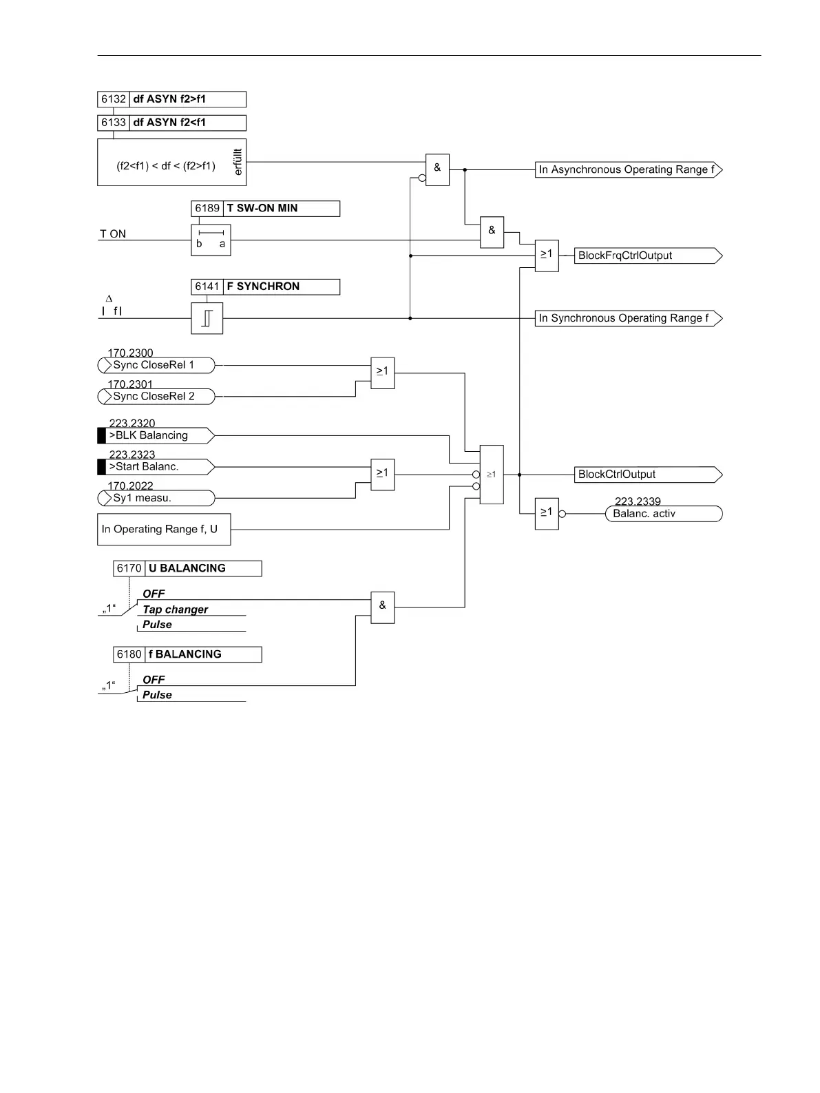
Figure 2-21
Logic diagram for blocking balancing commands
Output of Balancing Commands
If there are no blockages, a pulse time is computed and started on the basis of the parameter settings and the
particular difference values from the setpoint. After the impulse time has elapsed, the dead time is started. If
setpoints are exceeded during output, i.e. if the sign of the voltage or frequency difference changes, the
actuator pulse is aborted and after expiry of the dead time a pulse is started in the opposite direction.
Figure 2-22 shows the logic diagram for generation of the voltage actuator pulses, Figure 2-23 the logic
diagram for the generation of the frequency actuator pulses.
Functions
2.2 Paralleling Functions
SIPROTEC 4, 7VE61 and 7VE63, Manual 57
C53000-G1176-C163-3, Edition 10.2017

 Loading...


