[logik-stellbefehle-spannung-290403-kn, 1, en_GB]
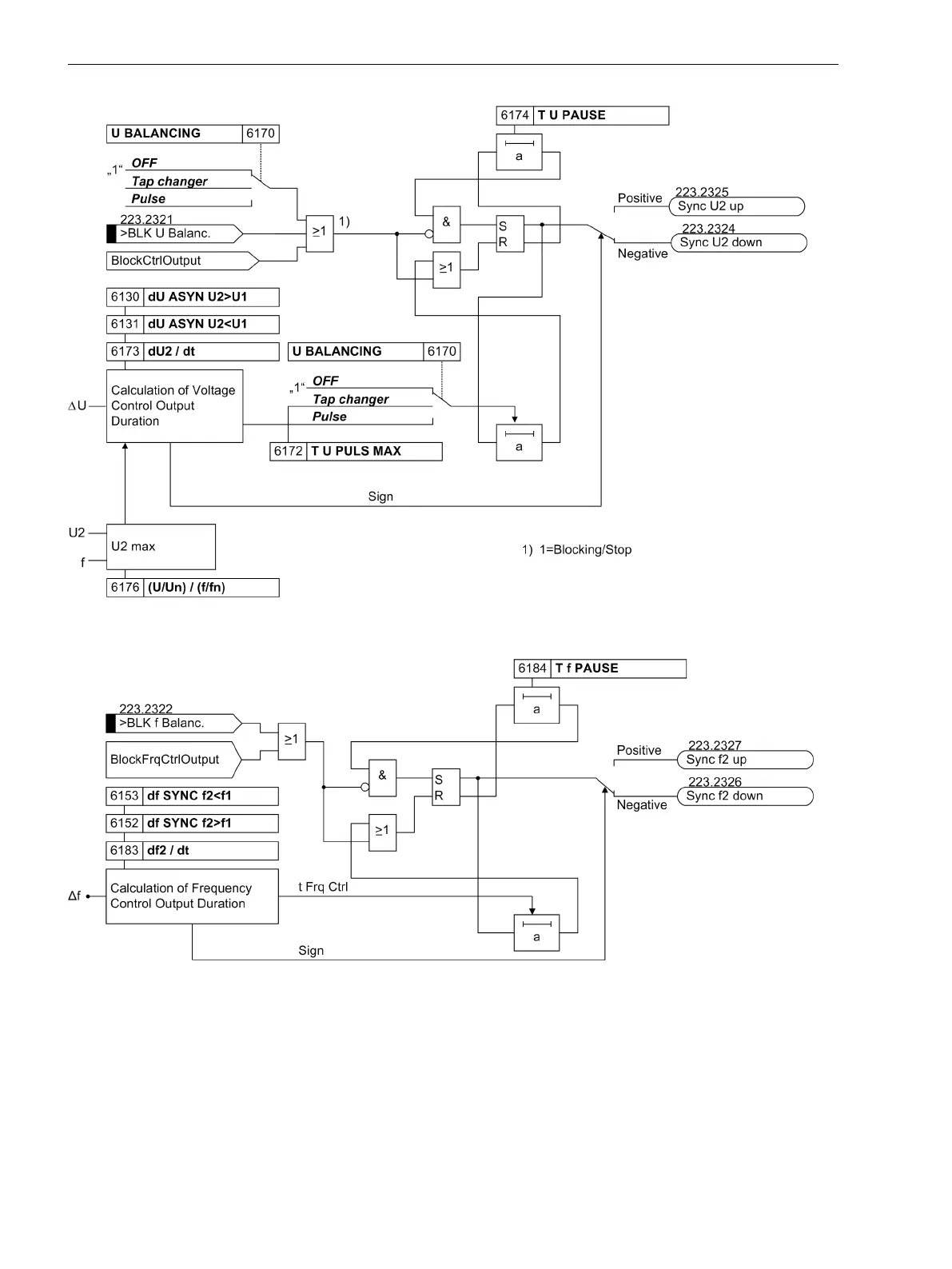
Figure 2-22
Logic diagram for generation of voltage balancing pulses
[logik-stellbefehle-frequenz-040303-oz, 1, en_GB]
Figure 2-23 Logic diagram for generation of frequency balancing pulses
If the synchronous operating range is detected, i.e. the frequency difference Δf is less than parameter 6141 F
SYNCHRON, the connection conditions however are not yet fulfilled (ΔU and Δα are not in the admissible
range), then “Kick impulses” may be issued if the voltage controllers will not converge within a short time. This
is the case if the time to synchronism exceeds a particular time.
If for the parameter 6132 df ASYN f2>f1 a nonzero value is set, i.e. parallel switching from the oversyn-
chronous range is permitted, then the target value 6188 Δf KICK should be set to a positive value because
kicking is done in the target value direction Δf KICK.
Functions
2.2 Paralleling Functions
58 SIPROTEC 4, 7VE61 and 7VE63, Manual
C53000-G1176-C163-3, Edition 10.2017

 Loading...


